对于BuildingWindowscontainerswithAWSCodePipelineandcustomactions感兴趣的读者,本文将会是一篇不错的选择,并为您提供关于(转载)Windows
对于Building Windows containers with AWS CodePipeline and custom actions感兴趣的读者,本文将会是一篇不错的选择,并为您提供关于(转载)Windows: "net use" command introduction、--Redis 入坑 --RedisPipelineException:Pipeline contained one or more invalid commands、Automated Refactoring from Mainframe to Serverless Functions and Containers with Blu Age、Automating model retraining and deployment using the AWS Step Functions Data Science SDK for Amaz...的有用信息。
本文目录一览:- Building Windows containers with AWS CodePipeline and custom actions
- (转载)Windows: "net use" command introduction
- --Redis 入坑 --RedisPipelineException:Pipeline contained one or more invalid commands
- Automated Refactoring from Mainframe to Serverless Functions and Containers with Blu Age
- Automating model retraining and deployment using the AWS Step Functions Data Science SDK for Amaz...

Building Windows containers with AWS CodePipeline and custom actions
https://amazonaws-china.com/blogs/devops/building-windows-containers-with-aws-codepipeline-and-custom-actions/
Dmitry Kolomiets, DevOps Consultant, Professional Services
AWS CodePipeline and AWS CodeBuild are the primary AWS services for building CI/CD pipelines. AWS CodeBuild supports a wide range of build scenarios thanks to various built-in Docker images. It also allows you to bring in your own custom image in order to use different tools and environment configurations. However, there are some limitations in using custom images.
Considerations for custom Docker images:
- AWS CodeBuild has to download a new copy of the Docker image for each build job, which may take longer time for large Docker images.
- AWS CodeBuild provides a limited set of instance types to run the builds. You might have to use a custom image if the build job requires higher memory, CPU, graphical subsystems, or any other functionality that is not part of the out-of-the-box provided Docker image.
Windows-specific limitations
- AWS CodeBuild supports Windows builds only in a limited number of AWS regions at this time.
- AWS CodeBuild executes Windows Server containers using Windows Server 2016 hosts, which means that build containers are huge—it is not uncommon to have an image size of 15 GB or more (with .NET Framework SDK installed). Windows Server 2019 containers, which are almost half as small, cannot be used due to host-container mismatch.
- AWS CodeBuild runs build jobs inside Docker containers. You should enable privileged mode in order to build and publish Linux Docker images as part of your build job. However, DIND is not supported on Windows and, therefore, AWS CodeBuild cannot be used to build Windows Server container images.
The last point is the critical one for microservice type of applications based on Microsoft stacks (.NET Framework, Web API, IIS). The usual workflow for this kind of applications is to build a Docker image, push it to ECR and update ECS / EKS cluster deployment.
Here is what I cover in this post:
- How to address the limitations stated above by implementing AWS CodePipeline custom actions (applicable for both Linux and Windows environments).
- How to use the created custom action to define a CI/CD pipeline for Windows Server containers.
CodePipeline custom actions
By using Amazon EC2 instances, you can address the limitations with Windows Server containers and enable Windows build jobs in the regions where AWS CodeBuild does not provide native Windows build environments. To accommodate the specific needs of a build job, you can pick one of the many Amazon EC2 instance types available.
The downside of this approach is additional management burden—neither AWS CodeBuild nor AWS CodePipeline support Amazon EC2 instances directly. There are ways to set up a Jenkins build cluster on AWS and integrate it with CodeBuild and CodeDeploy, but these options are too “heavy” for the simple task of building a Docker image.
There is a different way to tackle this problem: AWS CodePipeline provides APIs that allow you to extend a build action though custom actions. This example demonstrates how to add a custom action to offload a build job to an Amazon EC2 instance.
Here is the generic sequence of steps that the custom action performs:
- Acquire EC2 instance (see the Notes on Amazon EC2 build instances section).
- Download AWS CodePipeline artifacts from Amazon S3.
- Execute the build command and capture any errors.
- Upload output artifacts to be consumed by subsequent AWS CodePipeline actions.
- Update the status of the action in AWS CodePipeline.
- Release the Amazon EC2 instance.
Notice that most of these steps are the same regardless of the actual build job being executed. However, the following parameters will differ between CI/CD pipelines and, therefore, have to be configurable:
- Instance type (t2.micro, t3.2xlarge, etc.)
- AMI (builds could have different prerequisites in terms of OS configuration, software installed, Docker images downloaded, etc.)
- Build command line(s) to execute (MSBuild script, bash, Docker, etc.)
- Build job timeout
Serverless custom action architecture
CodePipeline custom build action can be implemented as an agent component installed on an Amazon EC2 instance. The agent polls CodePipeline for build jobs and executes them on the Amazon EC2 instance. There is an example of such an agent on GitHub, but this approach requires installation and configuration of the agent on all Amazon EC2 instances that carry out the build jobs.
Instead, I want to introduce an architecture that enables any Amazon EC2 instance to be a build agent without additional software and configuration required. The architecture diagram looks as follows:
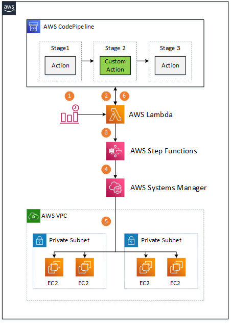
There are multiple components involved:
- An Amazon CloudWatch Event triggers an AWS Lambda function when a custom CodePipeline action is to be executed.
- The Lambda function retrieves the action’s build properties (AMI, instance type, etc.) from CodePipeline, along with location of the input artifacts in the Amazon S3 bucket.
- The Lambda function starts a Step Functions state machine that carries out the build job execution, passing all the gathered information as input payload.
- The Step Functions flow acquires an Amazon EC2 instance according to the provided properties, waits until the instance is up and running, and starts an AWS Systems Manager command. The Step Functions flow is also responsible for handling all the errors during build job execution and releasing the Amazon EC2 instance once the Systems Manager command execution is complete.
- The Systems Manager command runs on an Amazon EC2 instance, downloads CodePipeline input artifacts from the Amazon S3 bucket, unzips them, executes the build script, and uploads any output artifacts to the CodePipeline-provided Amazon S3 bucket.
- Polling Lambda updates the state of the custom action in CodePipeline once it detects that the Step Function flow is completed.
The whole architecture is serverless and requires no maintenance in terms of software installed on Amazon EC2 instances thanks to the Systems Manager command, which is essential for this solution. All the code, AWS CloudFormation templates, and installation instructions are available on the GitHub project. The following sections provide further details on the mentioned components.
Custom Build Action
The custom action type is defined as an AWS::CodePipeline::CustomActionType resource as follows:
  Ec2BuildActionType:
    Type: AWS::CodePipeline::CustomActionType
    Properties:
      Category: !Ref CustomActionProviderCategory
      Provider: !Ref CustomActionProviderName
      Version: !Ref CustomActionProviderVersion
      ConfigurationProperties:
        - Name: ImageId
          Description: AMI to use for EC2 build instances.
          Key: true
          Required: true
          Secret: false
          Queryable: false
          Type: String
        - Name: InstanceType
          Description: Instance type for EC2 build instances.
          Key: true
          Required: true
          Secret: false
          Queryable: false
          Type: String
        - Name: Command
          Description: Command(s) to execute.
          Key: true
          Required: true
          Secret: false
          Queryable: false
          Type: String
        - Name: WorkingDirectory
          Description: Working directory for the command to execute.
          Key: true
          Required: false
          Secret: false
          Queryable: false
          Type: String
        - Name: OutputArtifactPath
          Description: Path of the file(-s) or directory(-es) to use as custom action output artifact.
          Key: true
          Required: false
          Secret: false
          Queryable: false
          Type: String
      InputArtifactDetails:
        MaximumCount: 1
        MinimumCount: 0
      OutputArtifactDetails:
        MaximumCount: 1
        MinimumCount: 0
      Settings:
        EntityUrlTemplate: !Sub "https://${AWS::Region}.console.aws.amazon.com/systems-manager/documents/${RunBuildJobOnEc2Instance}"
        ExecutionUrlTemplate: !Sub "https://${AWS::Region}.console.aws.amazon.com/states/home#/executions/details/{ExternalExecutionId}"
The custom action type is uniquely identified by Category, Provider name, and Version.
Category defines the stage of the pipeline in which the custom action can be used, such as build, test, or deploy. Check the AWS documentation for the full list of allowed values.
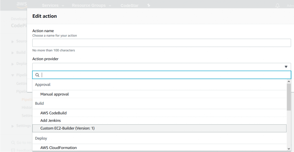
Provider name and Version are the values used to identify the custom action type in the CodePipeline console or AWS CloudFormation templates. Once the custom action type is installed, you can add it to the pipeline, as shown in the following screenshot:
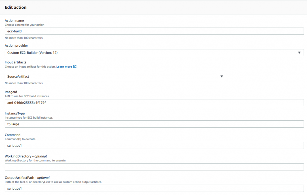
The custom action type also defines a list of user-configurable properties—these are the properties identified above as specific for different CI/CD pipelines:
- AMI Image ID
- Instance Type
- Command
- Working Directory
- Output artifacts
The properties are configurable in the CodePipeline console, as shown in the following screenshot:
Note the last two settings in the Custom Action Type AWS CloudFormation definition: EntityUrlTemplate and ExecutionUrlTemplate.
EntityUrlTemplate defines the link to the AWS Systems Manager document that carries over the build actions. The link is visible in AWS CodePipeline console as shown in the following screenshot:
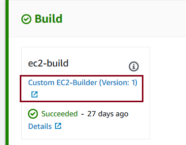
ExecutionUrlTemplate defines the link to additional information related to a specific execution of the custom action. The link is also visible in the CodePipeline console, as shown in the following screenshot:

This URL is defined as a link to the Step Functions execution details page, which provides high-level information about the custom build step execution, as shown in the following screenshot:
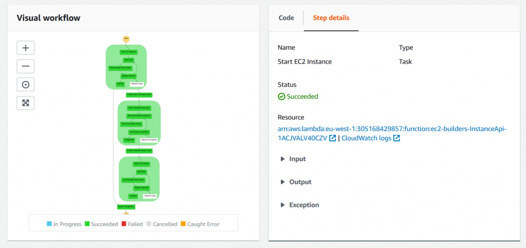
This page is a convenient visual representation of the custom action execution flow and may be useful for troubleshooting purposes as it gives an immediate access to error messages and logs.
The polling Lambda function
The Lambda function polls CodePipeline for custom actions when it is triggered by the following CloudWatch event:
  source:
    - "aws.codepipeline"
  detail-type:
    - "CodePipeline Action Execution State Change"
  detail:
    state:
      - "STARTED"
The event is triggered for every CodePipeline action started, so the Lambda function should verify if, indeed, there is a custom action to be processed.
The rest of the lambda function is trivial and relies on the following APIs to retrieve or update CodePipeline actions and deal with instances of Step Functions state machines:
CodePipeline API
- poll_for_jobs
- acknowledge_job
- put_job_success_result
- put_job_failure_result
AWS Step Functions API
- start_execution
- describe_execution
You can find the complete source of the Lambda function on GitHub.
Step Functions state machine
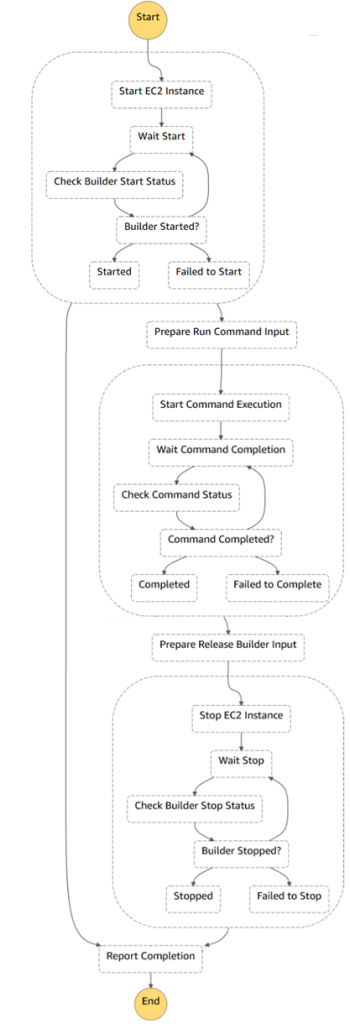
The following diagram shows complete Step Functions state machine. There are three main blocks on the diagram:
- Acquiring an Amazon EC2 instance and waiting while the instance is registered with Systems Manager
- Running a Systems Manager command on the instance
- Releasing the Amazon EC2 instance
Note that it is necessary to release the Amazon EC2 instance in case of error or exception during Systems Manager command execution, relying on Fallback States to guarantee that.
You can find the complete definition of the Step Function state machine on GitHub.
Systems Manager Document
The AWS Systems Manager Run Command does all the magic. The Systems Manager agent is pre-installed on AWS Windows and Linux AMIs, so no additional software is required. The Systems Manager run command executes the following steps to carry out the build job:
- Download input artifacts from Amazon S3.
- Unzip artifacts in the working folder.
- Run the command.
- Upload output artifacts to Amazon S3, if any; this makes them available for the following CodePipeline stages.
The preceding steps are operating-system agnostic, and both Linux and Windows instances are supported. The following code snippet shows the Windows-specific steps.
You can find the complete definition of the Systems Manager document on GitHub.
mainSteps:
  - name: win_enable_docker
    action: aws:configureDocker
    inputs:
      action: Install

  # Windows steps
  - name: windows_script
    precondition:
      StringEquals: [platformType, Windows]
    action: aws:runPowerShellScript
    inputs:
      runCommand:
        # Ensure that if a command fails the script does not proceed to the following commands
        - "$ErrorActionPreference = \"Stop\""

        - "$jobDirectory = \"{{ workingDirectory }}\""
        # Create temporary folder for build artifacts, if not provided
        - "if ([string]::IsNullOrEmpty($jobDirectory)) {"
        - "    $parent = [System.IO.Path]::GetTempPath()"
        - "    [string] $name = [System.Guid]::NewGuid()"
        - "    $jobDirectory = (Join-Path $parent $name)"
        - "    New-Item -ItemType Directory -Path $jobDirectory"
                # Set current location to the new folder
        - "    Set-Location -Path $jobDirectory"
        - "}"

        # Download/unzip input artifact
        - "Read-S3Object -BucketName {{ inputBucketName }} -Key {{ inputObjectKey }} -File artifact.zip"
        - "Expand-Archive -Path artifact.zip -DestinationPath ."

        # Run the build commands
        - "$directory = Convert-Path ."
        - "$env:PATH += \";$directory\""
        - "{{ commands }}"
        # We need to check exit code explicitly here
        - "if (-not ($?)) { exit $LASTEXITCODE }"

        # Compress output artifacts, if specified
        - "$outputArtifactPath  = \"{{ outputArtifactPath }}\""
        - "if ($outputArtifactPath) {"
        - "    Compress-Archive -Path $outputArtifactPath -DestinationPath output-artifact.zip"
                # Upload compressed artifact to S3
        - "    $bucketName = \"{{ outputBucketName }}\""
        - "    $objectKey = \"{{ outputObjectKey }}\""
        - "    if ($bucketName -and $objectKey) {"
                    # Don''t forget to encrypt the artifact - CodePipeline bucket has a policy to enforce this
        - "        Write-S3Object -BucketName $bucketName -Key $objectKey -File output-artifact.zip -ServerSideEncryption aws:kms"
        - "    }"
        - "}"
      workingDirectory: "{{ workingDirectory }}"
      timeoutSeconds: "{{ executionTimeout }}"
CI/CD pipeline for Windows Server containers
Once you have a custom action that offloads the build job to the Amazon EC2 instance, you may approach the problem stated at the beginning of this blog post: how to build and publish Windows Server containers on AWS.
With the custom action installed, the solution is quite straightforward. To build a Windows Server container image, you need to provide the value for Windows Server with Containers AMI, the instance type to use, and the command line to execute, as shown in the following screenshot:
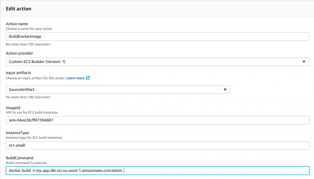
This example executes the Docker build command on a Windows instance with the specified AMI and instance type, using the provided source artifact. In real life, you may want to keep the build script along with the source code and push the built image to a container registry. The following is a PowerShell script example that not only produces a Docker image but also pushes it to AWS ECR:
# Authenticate with ECR
Invoke-Expression -Command (Get-ECRLoginCommand).Command

# Build and push the image
docker build -t <ecr-repository-url>:latest .
docker push <ecr-repository-url>:latest

return $LASTEXITCODE
You can find a complete example of the pipeline that produces the Windows Server container image and pushes it to Amazon ECR on GitHub.
Notes on Amazon EC2 build instances
There are a few ways to get Amazon EC2 instances for custom build actions. Let’s take a look at a couple of them below.
Start new EC2 instance per job and terminate it at the end
This is a reasonable default strategy that is implemented in this GitHub project. Each time the pipeline needs to process a custom action, you start a new Amazon EC2 instance, carry out the build job, and terminate the instance afterwards.
This approach is easy to implement. It works well for scenarios in which you don’t have many builds and/or builds take some time to complete (tens of minutes). In this case, the time required to provision an instance is amortized. Conversely, if the builds are fast, instance provisioning time could be actually longer than the time required to carry out the build job.
Use a pool of running Amazon EC2 instances
There are cases when it is required to keep builder instances “warm”, either due to complex initialization or merely to reduce the build duration. To support this scenario, you could maintain a pool of always-running instances. The “acquisition” phase takes a warm instance from the pool and the “release” phase returns it back without terminating or stopping the instance. A DynamoDB table can be used as a registry to keep track of “busy” instances and provide waiting or scaling capabilities to handle high demand.
This approach works well for scenarios in which there are many builds and demand is predictable (e.g. during work hours).
Use a pool of stopped Amazon EC2 instances
This is an interesting approach, especially for Windows builds. All AWS Windows AMIs are generalized using a sysprep tool. The important implication of this is that the first start time for Windows EC2 instances is quite long: it could easily take more than 5 minutes. This is generally unacceptable for short-living build jobs (if your build takes just a minute, it is annoying to wait 5 minutes to start the instance).
Interestingly, once the Windows instance is initialized, subsequent starts take less than a minute. To utilize this, you could create a pool of initialized and stopped Amazon EC2 instances. In this case, for the acquisition phase, you start the instance, and when you need to release it, you stop or hibernate it.
This approach provides substantial improvements in terms of build start-up time.
The downside is that you reuse the same Amazon EC2 instance between the builds—it is not completely clean environment. Build jobs have to be designed to expect the presence of artifacts from the previous executions on the build instance.
Using an Amazon EC2 fleet with spot instances
Another variation of the previous strategies is to use Amazon EC2 Fleet to make use of cost-efficient spot instances for your build jobs.
Amazon EC2 Fleet makes it possible to combine on-demand instances with spot instances to deliver cost-efficient solution for your build jobs. On-demand instances can provide the minimum required capacity and spot instances provide a cost-efficient way to improve performance of your build fleet.
Note that since spot instances could be terminated at any time, the Step Functions workflow has to support Amazon EC2 instance termination and restart the build on a different instance transparently for CodePipeline.
Limits and Cost
The following are a few final thoughts.
Custom action timeouts
The default maximum execution time for CodePipeline custom actions is one hour. If your build jobs require more than an hour, you need to request a limit increase for custom actions.
Cost of running EC2 build instances
Custom Amazon EC2 instances could be even more cost effective than CodeBuild for many scenarios. However, it is difficult to compare the total cost of ownership of a custom-built fleet with CodeBuild. CodeBuild is a fully managed build service and you pay for each minute of using the service. In contrast, with Amazon EC2 instances you pay for the instance either per hour or per second (depending on instance type and operating system), EBS volumes, Lambda, and Step Functions. Please use the AWS Simple Monthly Calculator to get the total cost of your projected build solution.
Cleanup
If you are running the above steps as a part of workshop / testing, then you may delete the resources to avoid any further charges to be incurred. All resources are deployed as part of CloudFormation stack, so go to the Services, CloudFormation, select the specific stack and click delete to remove the stack.
Conclusion
The CodePipeline custom action is a simple way to utilize Amazon EC2 instances for your build jobs and address a number of CodePipeline limitations.
With AWS CloudFormation template available on GitHub you can import the CodePipeline custom action with a simple Start/Terminate instance strategy into your account and start using the custom action in your pipelines right away.
The CodePipeline custom action with a simple Start/Terminate instance strategy is available on GitHub as an AWS CloudFormation stack. You could import the stack to your account and start using the custom action in your pipelines right away.
An example of the pipeline that produces Windows Server containers and pushes them to Amazon ECR can also be found on GitHub.
I invite you to clone the repositories to play with the custom action, and to make any changes to the action definition, Lambda functions, or Step Functions flow.
Feel free to ask any questions or comments below, or file issues or PRs on GitHub to continue the discussion.
Windows:")
(转载)Windows: "net use" command introduction
1)建立空连接:
net use ""IP"ipc$ "" /user:"" (一定要注意:这一行命令中包含了3个空格)
2)建立非空连接:
net use ""IP"ipc$ "密码" /user:"用户名" (同样有3个空格)
3)映射默认共享:
net use z: ""IP"c$ "密码" /user:"用户名" (即可将对方的c盘映射为自己的z盘,其他盘类推)
如果已经和目标建立了ipc$,则可以直接用IP+盘符+$访问,具体命令 net use z: ""IP"c$
4)删除一个ipc$连接
net use ""IP"ipc$ /del
5)删除共享映射
net use c: /del 删除映射的c盘,其他盘类推
net use * /del 删除全部,会有提示要求按y确认
3 查看远程主机的共享资源(但看不到默认共享)
net view ""IP
4 查看本地主机的共享资源(可以看到本地的默认共享)
net share
5 得到远程主机的用户名列表
nbtstat -A IP
6 得到本地主机的用户列表
net user
7 查看远程主机的当前时间
net time ""IP
8 显示本地主机当前服务
net start
9 启动/关闭本地服务
net start 服务名 /y
net stop 服务名 /y
10 映射远程共享:
net use z: ""IP"baby
此命令将共享名为baby的共享资源映射到z盘
11 删除共享映射
net use c: /del 删除映射的c盘,其他盘类推
net use * /del /y删除全部
12 向远程主机复制文件
copy "路径"srv.exe ""IP"共享目录名,如:
copy ccbirds.exe ""*.*.*.*"c 即将当前目录下的文件复制到对方c盘内
13 远程添加计划任务
at ""ip 时间 程序名,如:
at ""127.0.0.0 11:00 love.exe
注意:时间尽量使用24小时制;在系统默认搜索路径(比如system32/)下不用加路径,否则必须加全路径
14 开启远程主机的telnet
这里要用到一个小程序:opentelnet.exe,各大下载站点都有,而且还需要满足四个要求:
1)目标开启了ipc$共享
2)你要拥有管理员密码和帐号
3)目标开启RemoteRegistry服务,用户就该ntlm认证
4)对WIN2K/XP有效,NT未经测试
命令格式:OpenTelnet.exe ""server account psw NTLM认证方式 port
试例如下:c:">OpenTelnet.exe ""*.*.*.* administrator "" 1 90
15 激活用户/加入管理员组
1 net uesr account /active:yes
2 net localgroup administrators account /add
16 关闭远程主机的telnet
同样需要一个小程序:ResumeTelnet.exe
命令格式:ResumeTelnet.exe ""server account psw
试例如下:c:">ResumeTelnet.exe ""*.*.*.* administrator ""
17 删除一个已建立的ipc$连接
net use ""IP"ipc$ /del

--Redis 入坑 --RedisPipelineException:Pipeline contained one or more invalid commands
异常说明
最近在写代码的时候,redis 报了如下错误:
org.springframework.data.redis.connection.RedisPipelineException: Pipeline contained one or more invalid commands; nested exception is io.lettuce.core.RedisCommandException: WRONGTYPE Operation against a key holding the wrong kind of value
原因分析
之前的一个需求中,使用的是 list 作为数据结构进行存储,其存储方式为 redisService.lPush (key,value),之后逻辑的变更,使得需要换成 set 作为数据结构进行存储,其存储方式为 redisService.sadd (key,value)。发生错误的位置就是这里:
在更改数据结构存储的同时,key 的键还是一样的,因为之前的键是绑定给 list 结构的,现在 key 没变,而结构换成了 set,所以导致类型错误的异常。
解决方法
只需要把键重新命名为新的并且不重复于其他键即可。
总结
在使用 redis 进行存储的时候,数据结构最好不要随意更改,如果更改了,就需要把键重新命名一下,以防键的类型与原来的不匹配,存储从而导致发生异常。
————————————————

Automated Refactoring from Mainframe to Serverless Functions and Containers with Blu Age
https://amazonaws-china.com/blogs/apn/automated-refactoring-from-mainframe-to-serverless-functions-and-containers-with-blu-age/
By Alexis Henry, Chief Technology Officer at Blu Age
By Phil de Valence, Principal Solutions Architect for Mainframe Modernization at AWS
 |
 |
Mainframe workloads are often tightly-coupled legacy monoliths with millions of lines of code, and customers want to modernize them for business agility.
Manually rewriting a legacy application for a cloud-native architecture requires re-engineering use cases, functions, data models, test cases, and integrations. For a typical mainframe workload with millions of lines of code, this involves large teams over long periods of time, which can be risky and cost-prohibitive.
Fortunately, Blu Age Velocity accelerates the mainframe transformation to agile serverless functions or containers. It relies on automated refactoring and preserves the investment in business functions while expediting the reliable transition to newer languages, data stores, test practices, and cloud services.
Blu Age is an AWS Partner Network (APN) Select Technology Partner that helps organizations enter the digital era by modernizing legacy systems while substantially reducing modernization costs, shortening project duration, and mitigating the risk of failure.
In this post, we’ll describe how to transform a typical mainframe CICS application to Amazon Web Services (AWS) containers and AWS Lambda functions. We’ll show you how to increase mainframe workload agility with refactoring to serverless and containers.
Customer Drivers
There are two main drivers for mainframe modernization with AWS: cost reduction and agility. Agility has many facets related to the application, underlying infrastructure, and modernization itself.
On the infrastructure agility side, customers want to go away from rigid mainframe environments in order to benefit from the AWS Cloud’s elastic compute, managed containers, managed databases, and serverless functions on a pay-as-you-go model.
They want to leave the complexity of these tightly-coupled systems in order to increase speed and adopt cloud-native architectures, DevOps best practices, automation, continuous integration and continuous deployment (CI/CD), and infrastructure as code.
On the application agility side, customers want to stay competitive by breaking down slow mainframe monoliths into leaner services and microservices, while at the same time unleashing the mainframe data.
Customers also need to facilitate polyglot architectures where development teams decide on the most suitable programming language and stack for each service.
Some customers employ large teams of COBOL developers with functional knowledge that should be preserved. Others suffer from the mainframe retirement skills gap and have to switch to more popular programming languages quickly.
Customers also require agility in the transitions. They want to choose when and how fast they execute the various transformations, and whether they’re done simultaneously or independently.
For example, a transition from COBOL to Java is not only a technical project but also requires transitioning code development personnel to the newer language and tools. It can involve retraining and new hiring.
A transition from mainframe to AWS should go at a speed which reduces complexity and minimizes risks. A transition to containers or serverless functions should be up to each service owner to decide. A transition to microservices needs business domain analysis, and consequently peeling a monolith is done gradually over time.
This post shows how Blu Age automated refactoring accelerates the customer journey to reach a company’s desired agility with cloud-native architectures and microservices. Blu Age does this by going through incremental transitions at a customer’s own pace.
Sample Mainframe COBOL Application
Let’s look at a sample application of a typical mainframe workload that we will then transform onto AWS.
This application is a COBOL application that’s accessed by users via 3270 screens defined by CICS BMS maps. It stores data in a DB2 z/OS relational database and in VSAM indexed files, using CICS Temporary Storage (TS) queues.
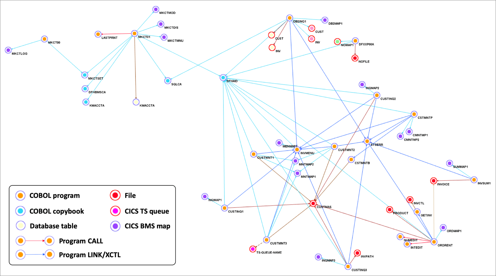
Figure 1 – Sample COBOL CICS application showing file dependencies.
We use Blu Age Analyzer to visualize the application components such as programs, copybooks, queues, and data elements.
Figure 1 above shows the Analyzer display. Each arrow represents a program call or dependency. You can see the COBOL programs using BMS maps for data entry and accessing data in DB2 database tables or VSAM files.
You can also identify the programs which are data-independent and those which access the same data file. This information helps define independent groupings that facilitate the migration into smaller services or even microservices.
This Analyzer view allows customers to identify the approach, groupings, work packages, and transitions for the automated refactoring.
In the next sections, we describe how to do the groupings and the transformation for three different target architectures: compute with Amazon Elastic Compute Cloud (Amazon EC2), containers with Amazon Elastic Kubernetes Service (Amazon EKS), and serverless functions with AWS Lambda.
Automated Refactoring to Elastic Compute
First, we transform the mainframe application to be deployed on Amazon EC2. This provides infrastructure agility with a large choice of instance types, horizontal scalability, auto scaling, some managed services, infrastructure automation, and cloud speed.
Amazon EC2 also provides some application agility with DevOps best practices, CI/CD pipeline, modern accessible data stores, and service-enabled programs.
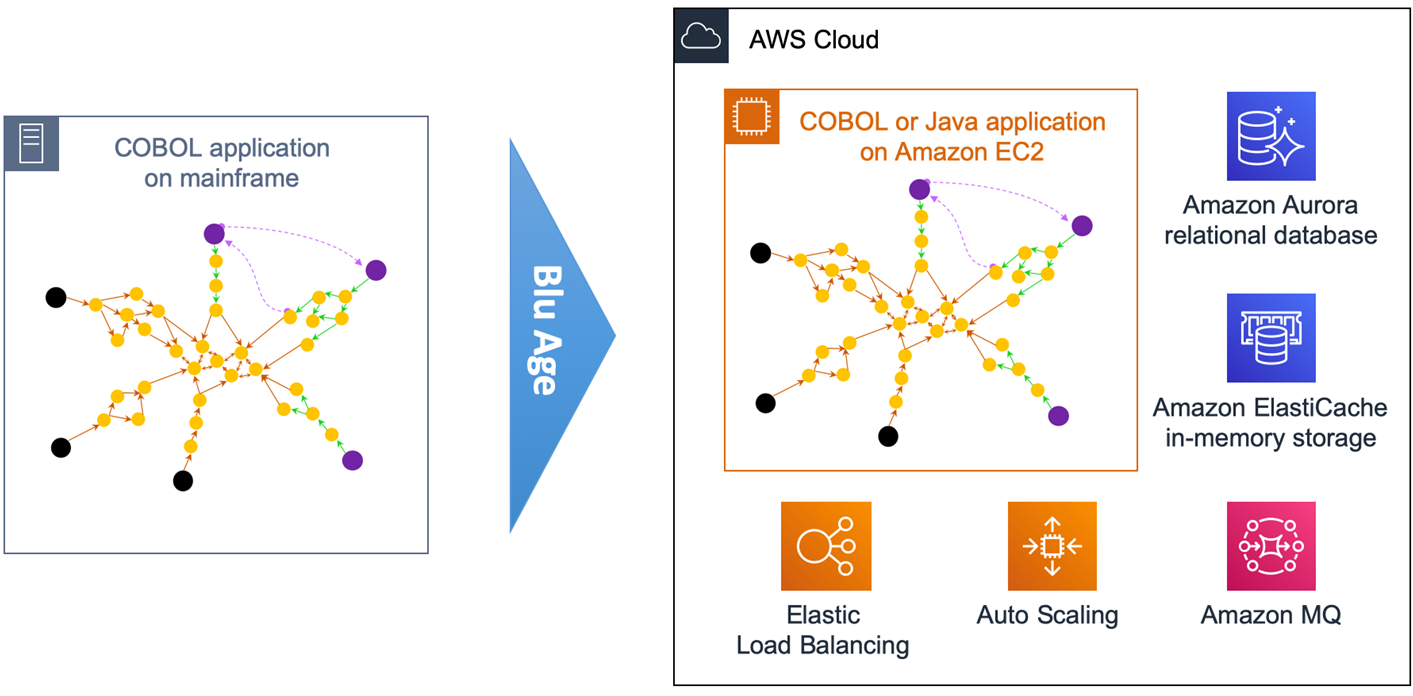
Figure 2 – Overview of automated refactoring from mainframe to Amazon EC2.
Figure 2 above shows the automated refactoring of the mainframe application to Amazon EC2.
The DB2 tables and VSAM files are refactored to Amazon Aurora relational database. Amazon ElastiCache is used for in-memory temporary storage or for performance acceleration, and Amazon MQ takes care of the messaging communications.
Once refactored, the application becomes stateless and elastic across many duplicate Amazon EC2 instances that benefit from Auto Scaling Groups and Elastic Load Balancing (ELB). The application code stays monolithic in this first transformation.
With such monolithic transformation, all programs and dependencies are kept together. That means we create only one grouping.
Figure 3 below shows the yellow grouping that includes all application elements. Using Blu Age Analyzer, we define groupings by assigning a common tag to multiple application elements.
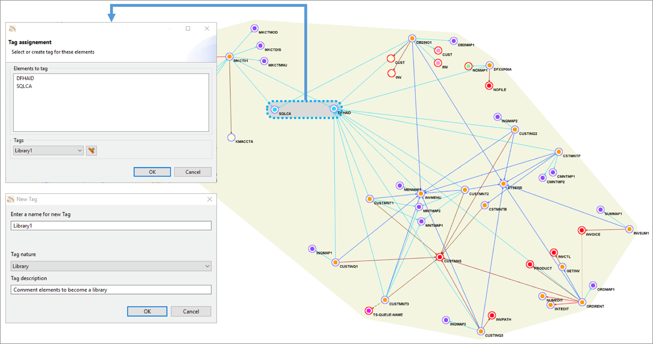
Figure 3 – Blu Age Analyzer with optional groupings for work packages and libraries.
With larger applications, it’s very likely we’d break down the larger effort by defining incremental work packages. Each work package is associated with one grouping and one tag.
Similarly, some shared programs or copybooks can be externalized and shared using a library. Each library is associated with one grouping and one tag. For example, in Figure 3 one library is created based on two programs, as shown by the grey grouping.
Ultimately, once the project is complete, all programs and work packages are deployed together within the same Amazon EC2 instances.
For each tag, we then export the corresponding application elements to Git.
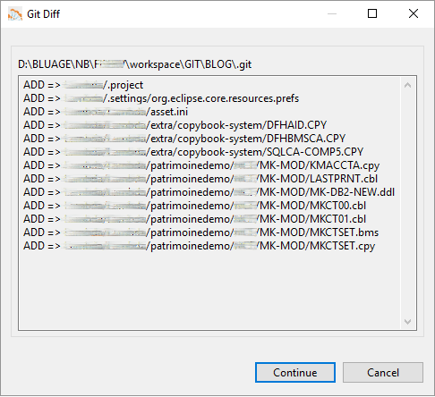
Figure 4 – Blu Age Analyzer export to Git.
Figure 4 shows the COBOL programs, copybooks, DB2 Data Definition Language (DDL), and BMS map being exported to Git.
As you can see in Figure 5 below, the COBOL application elements are available in the Integrated Development Environment (IDE) for maintenance, or for new development and compilation.
Blu Age toolset allows maintaining the migrated code in either in COBOL or in Java.
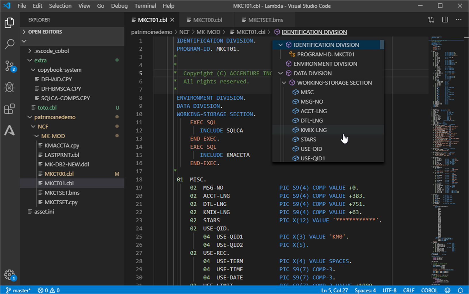
Figure 5 – Integrated Development Environment with COBOL application.
The code is recompiled and automatically packaged for the chosen target Amazon EC2 deployment.
During this packaging, the compute code is made stateless with any shared or persistent data externalized to data stores. This follows many of The Twelve-Factor App best practices that enable higher availability, scalability, and elasticity on the AWS Cloud.
In parallel, based on the code refactoring, the data from VSAM and DB2 z/OS is converted to the PostgreSQL-compatible edition of Amazon Aurora with corresponding data access queries conversions. Blu Age Velocity also generates the scripts for data conversion and migration.
Once deployed, the code and data go through unit, integration, and regression testing in order to validate functional equivalence. This is part of an automated CI/CD pipeline which also includes quality and security gates. The application is now ready for production on elastic compute.
Automated Refactoring to Containers
In this section, we increase agility by transforming the mainframe application to be deployed as different services in separate containers managed by Amazon EKS.
The application agility increases because the monolith is broken down into different services that can evolve and scale independently. Some services execute online transactions for users’ direct interactions. Some services execute batch processing. All services run in separate containers in Amazon EKS.
With such an approach, we can create microservices with both independent data stores and independent business functionalities. Read more about How to Peel Mainframe Monoliths for AWS Microservices with Blu Age.
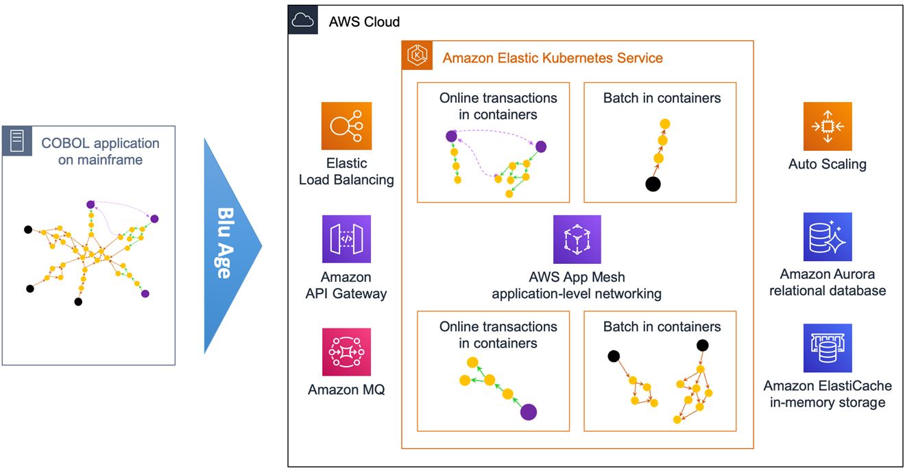
Figure 6 – Overview of automated refactoring from mainframe to Amazon EKS.
Figure 6 shows the automated refactoring of the mainframe application to Amazon EKS. You could also use Amazon Elastic Container Service (Amazon ECS) and AWS Fargate.
The mainframe application monolith is broken down targeting different containers for various online transactions, and different containers for various batch jobs. Each service DB2 tables and VSAM files are refactored to their own independent Amazon Aurora relational database.
AWS App Mesh facilitates internal application-level communication, while Amazon API Gateway and Amazon MQ focus more on the external integration.
With the Blu Age toolset, some services can still be maintained and developed in COBOL while others can be maintained in Java, which simultaneously allows a polyglot architecture.
For the application code maintained in COBOL on AWS, Blu Age Serverless COBOL provides native integration COBOL APIs for AWS services such as Amazon Aurora, Amazon Relational Database Service (Amazon RDS), Amazon DynamoDB, Amazon ElastiCache, and Amazon Kinesis, among others.
With such refactoring, programs and dependencies are grouped into separate services. This is called service decomposition and means we create multiple groupings in Blu Age Analyzer.
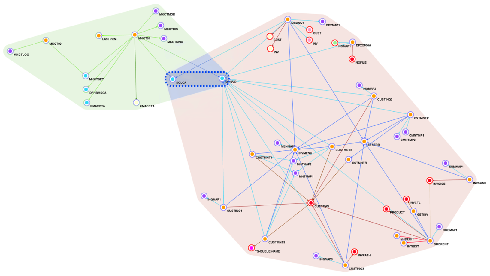
Figure 7 – Blu Age Analyzer with two services groupings and one library grouping.
Figure 7 shows one service grouping in green, another service grouping in rose, and a library grouping in blue. Groupings are formalized with one tag each.
For each tag, we export the corresponding application elements to Git and open them in the IDE for compilation. We can create one Git project per tag providing independence and agility to individual service owner.
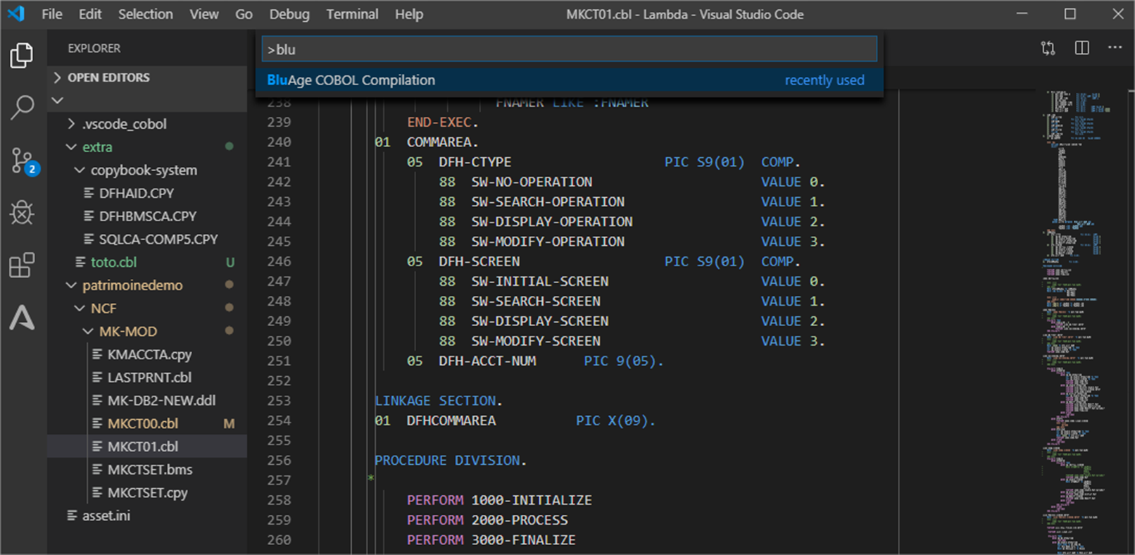
Figure 8 – COBOL program in IDE ready for compilation.
The Blu Age compiler for containers compiles the code and packages it into a Docker container image with all the necessary language runtime configuration for deployment and services communication.
The REST APIs for communication are automatically generated. The container images are automatically produced, versioned and stored into Amazon Elastic Container Registry (Amazon ECR), and the two container images are deployed onto Amazon EKS.
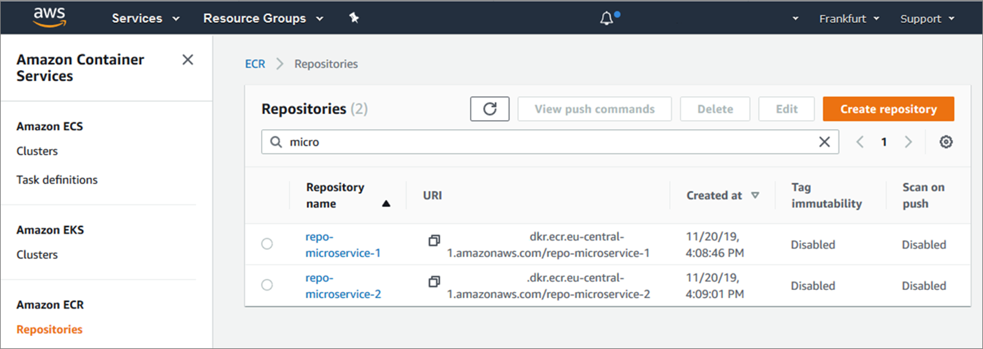
Figure 9 – AWS console showing the two container images created in Amazon ECR.
Figure 9 above shows the two new Docker container images referenced in Amazon ECR.
After going through data conversion and extensive testing similar to the previous section, the application is now ready for production on containers managed by Amazon EKS.
Automated Refactoring to Serverless Functions
Now, we can increase agility and cost efficiency further by targeting serverless functions in AWS Lambda.
Not only is the monolith broken down into separate services, but the services become smaller functions with no need to manage servers or containers. With Lambda, there’s no charge when the code is not running.
Not all programs are good use-cases for Lambda. Technical characteristics make Lambda better suited for short-lived lightweight stateless functions. For this reason, some services are deployed in Lambda while others are still deployed in containers or elastic compute.
For example, long-running batch processing cannot run in Lambda but they can run in containers. Online transactions or batch-specific short functions, on the other hand, can run in Lambda.
With this approach, we can create granular microservices with independent data stores and business functions.
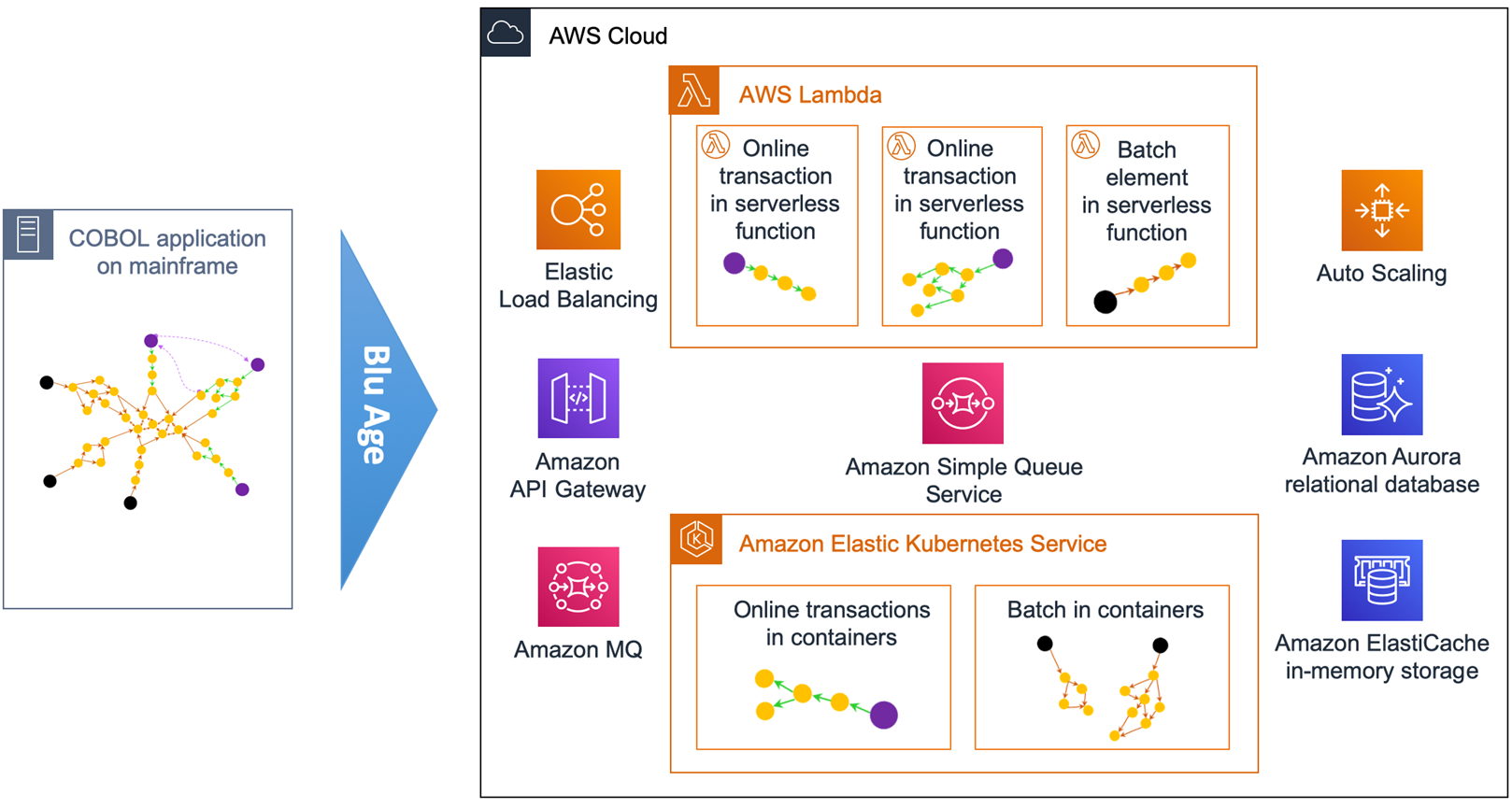
Figure 10 – Overview of automated refactoring from mainframe to AWS Lambda.
Figure 10 shows the automated refactoring of the mainframe application to Lambda and Amazon EKS. Short-lived stateless transactions and programs are deployed in Lambda, while long-running or unsuitable programs run in Docker containers within Amazon EKS.
Amazon Simple Queue Service (SQS) is used for service calls within or across Lambda and Amazon EKS. Such architecture is similar to a cloud-native application architecture that’s much better positioned in the Cloud-Native Maturity Model.
With this refactoring, programs and dependencies are grouped into more separate services in Blu Age Analyzer.
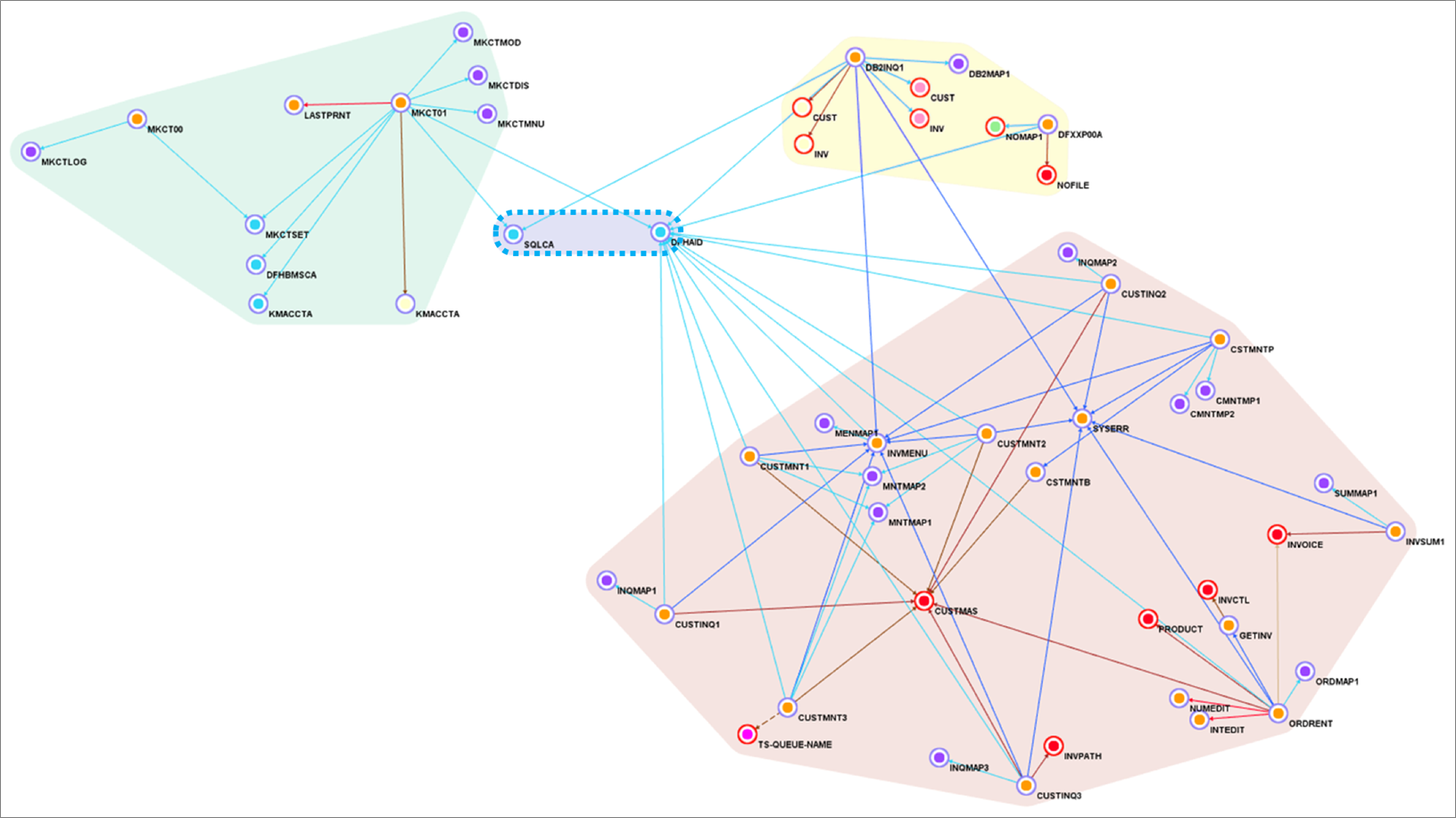
Figure 11 – Blu Age Analyzer with two AWS Lambda groupings, on container grouping and one library grouping.
In Figure 11 above, the green grouping and yellow grouping are tagged for Lambda deployment. The rose grouping stays tagged for container deployment, while the blue grouping stays a library. Same as before, the code is exported tag after tag into Git, then opened within the IDE for compilation.
The compilation and deployment for Lambda does not create a container image, but it creates compiled code ready to be deployed on Blu Age Serverless COBOL layer for Lambda.
Here’s the Serverless COBOL layer added to the deployed functions.
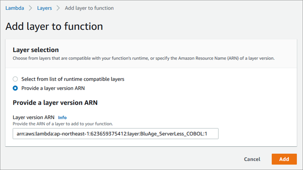
Figure 12 – Blu Age Serverless COBOL layer added to AWS Lambda function.
Now, here’s the two new Lambda functions created once the compiled code is deployed.

Figure 13 – AWS console showing the two AWS Lambda functions created.
After data conversion and thorough testing similar to the previous sections, the application is now ready for production on serverless functions and containers.
With business logic in Lambda functions, this logic can be invoked from many sources (REST APIs, messaging, object store, streams, databases) for innovations.
Incremental Transitions
Automated refactoring allows customers to accelerate modernization and minimize project risks on many dimensions.
On one side, the extensive automation for the full software stack conversion including code, data formats, dependencies provides functional equivalence preserving core business logic.
On the other side, the solution provides incremental transitions and accelerators tailored to the customer constraints and objectives:
- Incremental transition from mainframe to AWS: As shown with Blu Age Analyzer, a large application migration is piece-mealed into small work packages with coherent programs and data elements. The migration does not have to be a big bang, and it can be executed incrementally over time.
. - Incremental transition from COBOL to Java: Blu Age compilers and toolset supports maintaining the application code either in the original COBOL or Java.
.
All the deployment options described previously can be maintained similarly in COBOL or in Java and co-exist. That means you can choose to keep developing in COBOL if appropriate, and decide to start developing in Java when convenient facilitating knowledge transfer between developers.
. - Incremental transition from elastic compute, to containers, to functions: Some customers prefer starting with elastic compute, while others prefer jumping straight to containers or serverless functions. Blu Age toolset has the flexibility to switch from one target to the other following the customer specific needs.
. - Incremental transition from monolith to services and microservices: Peeling a large monolith is a long process, and the monolith can be kept and deployed on the various compute targets. When time comes, services or microservices are identified in Blu Age Analyzer, and then extracted and deployed on elastic compute, containers, or serverless functions.
From a timeline perspective, the incremental transition from mainframe to AWS is a short-term project with achievable return on investment, as shown on Figure 14.
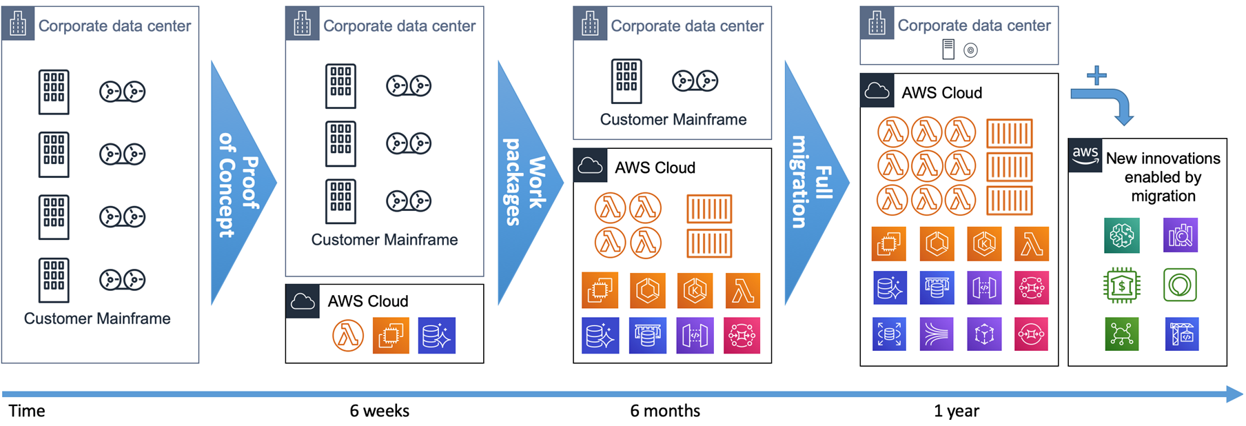
Figure 14 – Mainframe to AWS transition timeline.
We recommend starting with a hands-on Proof-of-Concept (PoC) with customers’ real code. It’s the only way to prove the technical viability and show the outcome quality within 6 weeks.
Then, you can define work packages and incrementally refactor the mainframe application to AWS targeting elastic compute, containers, or serverless functions.
The full refactoring of a mainframe workload onto AWS can be completed in a year. As soon as services are refactored and in production on AWS, new integrations and innovations become possible for analytics, mobile, voice, machine learning (ML), or Internet of Things (IoT) use cases.
Summary
Blu Age mainframe automated refactoring provides the speed and flexibility to meet the agility needs of customers. It leverages the AWS quality of service for high security, high availability, elasticity, and rich system management to meet or exceed the mainframe workloads requirements.
While accelerating modernization, Blu Age toolset allows incremental transitions adapting to customers priorities. It accelerates mainframe modernization to containers or serverless functions
Blu Age also gives the option to keep developing in COBOL or transition smoothly to Java. It facilitates the identification and extraction of microservices.
For more details, visit the Serverless COBOL page and contact Blu Age to learn more.
.

.
Blu Age – APN Partner Spotlight
Blu Age is an APN Select Technology Partner that helps organizations enter the digital era by modernizing legacy systems while substantially reducing modernization costs, shortening project duration, and mitigating the risk of failure.
Contact Blu Age | Solution Overview | AWS Marketplace
*Already worked with Blu Age? Rate this Partner
*To review an APN Partner, you must be an AWS customer that has worked with them directly on a project.

Automating model retraining and deployment using the AWS Step Functions Data Science SDK for Amaz...
https://amazonaws-china.com/blogs/machine-learning/automating-model-retraining-and-deployment-using-the-aws-step-functions-data-science-sdk-for-amazon-sagemaker/
As machine learning (ML) becomes a larger part of companies’ core business, there is a greater emphasis on reducing the time from model creation to deployment. In November of 2019, AWS released the AWS Step Functions Data Science SDK for Amazon SageMaker, an open-source SDK that allows developers to create Step Functions-based machine learning workflows in Python. You can now use the SDK to create reusable model deployment workflows with the same tools you use to develop models. You can find the complete notebook for this solution in the “automate_model_retraining_workflow” folder of our GitHub repo.
This post demonstrates the capabilities of the Data Science SDK with a common use case: scheduled model retraining and deployment. In this post, you create a serverless workflow to train an ML model, check the performance of the model against a validation dataset, and deploy the model to production if the model accuracy surpasses a set threshold. Finally, the post shows how to trigger a workflow based off a periodic schedule.
The following diagram shows the serverless workflow described above utilizing AWS Step Functions.

This post uses the following AWS services:
- AWS Step Functions allows you to coordinate several AWS services into a serverless workflow. You can design and run workflows in which the output of one step acts as the input to the next step, and embed error handling into the workflow.
- Amazon SageMaker is a fully managed service that provides developers and data scientists with the tools to build, train, and deploy different types of ML models.
- AWS Glue is a fully managed extract, transform, and load (ETL) service. You can point AWS Glue to a supported data store and it generates the code to extract and load it into your target data store. AWS Glue runs on a distributed Apache Spark environment, which allows you to take advantage of Spark without managing the infrastructure.
- AWS Lambda is a compute service that lets you run code without provisioning or managing servers. Lambda executes your code only when triggered and scales automatically, from a few requests per day to thousands per second.
- Amazon EventBridge is a serverless event bus that makes it easy to connect different SaaS applications, AWS services, and data from your applications.
Overview of the SDK
The SDK provides a new way to use AWS Step Functions. A Step Function is a state machine that consists of a series of discrete steps. Each step can perform work, make choices, initiate parallel execution, or manage timeouts. You can develop individual steps and use Step Functions to handle the triggering, coordination, and state of the overall workflow. Before the Data Science SDK, you had to define Step Functions using the JSON-based Amazon States Language. With the SDK, you can now easily create, execute, and visualize Step Functions using Python code.
This post provides an overview of the SDK, including how to create Step Function steps, work with parameters, integrate service-specific capabilities, and link these steps together to create and visualize a workflow. You can find several code examples throughout the post; however, we created a detailed Amazon SageMaker notebook of the entire process. For more information, see our GitHub repo.
Steps, parameters, and dynamic workflows
Within a Step Function, each step passes its output to the next. You can use these outputs in the following steps to create dynamic workflows. You can also pass input parameters for each Step Function execution. Parameters allow you to keep your workflow general so it can support other projects.
To use the SDK to define the required input parameters for your workflow, see the following code:
execution_input = ExecutionInput(schema={
    ''TrainingJobName'': str,
    ''GlueJobName'': str,
    ''ModelName'': str,
    ''EndpointName'': str,
    ''LambdaFunctionName'': str
})
Built-in service integrations
The Data Science SDK integrates with several AWS services. The integrations allow you to directly control the supported services, without needing to write API calls. This post uses the AWS Glue, Lambda, and Amazon SageMaker integrations. For more information, see AWS Step Functions Service Integrations.
For model retraining, you first need to retrieve the latest data. You also need to enrich raw data while saving it to a file type and location supported by your ML model. AWS Glue connects to most data stores, supports custom scripting in Python, and doesn’t require management of servers. Use AWS Glue to start your workflow by reading data from your production data store and writing the transformed data to Amazon S3.
The Data Science SDK makes it easy to add an AWS Glue job to your workflow. The AWS Glue job itself specifies the data source location, Python code for ETL, and file destination to use. All the SDK requires is the name of the AWS Glue job as a parameter for the GlueStartJobRunStep. For more information, see Getting Started with AWS Glue ETL on YouTube.
Use an input parameter so you can choose your AWS Glue job at runtime:
etl_step = steps.GlueStartJobRunStep(
    ''Extract, Transform, Load'',
    parameters={"JobName": execution_input[''GlueJobName'']}
)
After you extract and save the input data, train a model using the SDK’s TrainingStep. Amazon SageMaker handles the underlying compute resources, but you need to specify the algorithm, hyperparameters, and data sources for training. See the following code:
training_step = steps.TrainingStep(
    ''Model Training'',
    estimator=xgb,
    data={
      ''train'': sagemaker.s3_input(train_data, content_type=''csv''),
      ''validation'': sagemaker.s3_input(validation_data, content_type=''csv'')},
    job_name=execution_input[''TrainingJobName'']
)
The estimator in the preceding code, xgb, encapsulates the XGBoost algorithm and its hyperparameters. For more information about how to define an estimator, see the GitHub repo.
The Step Function workflow remains in the training step until training completes. Afterwards, it needs to retrieve the training results so that your workflow can branch based on the accuracy of the new model. Use a Step Functions LambdaStep to call Lambda to run a simple Python function that queries the Amazon SageMaker training job and returns the results. To add a Lambda state with the SDK, specify the function name and payload. This post uses JSON paths to select the TrainingJobName in the Lambda function payload so it knows which training job to query. See the following code:
lambda_step = steps.compute.LambdaStep(
    ''Query Training Results'',
    parameters={"FunctionName": execution_input[''LambdaFunctionName''],
        ''Payload'':{"TrainingJobName.$": "$.TrainingJobName"}
    }
)
To deploy the model after training, you need to create a model object and deployment configuration from the training artifacts using the ModelStep and EndpointConfigStep from the SDK. See the following code:
model_step = steps.ModelStep(
    ''Save Model'',
    model=training_step.get_expected_model(),
    model_name=execution_input[''ModelName''],
    result_path=''$.ModelStepResults''
)

endpoint_config_step = steps.EndpointConfigStep(
    "Create Model Endpoint Config",
    endpoint_config_name=execution_input[''ModelName''],
    model_name=execution_input[''ModelName''],
    initial_instance_count=1,
    instance_type=''ml.m4.xlarge''
)
Finally, the workflow can deploy the new model as a managed API endpoint using the EndpointStep. The “update” parameter causes it to update an existing Amazon SageMaker endpoint as opposed to creating a new one. See the following code:
endpoint_step = steps.EndpointStep(
    ''Update Model Endpoint'',
    endpoint_name=execution_input[''EndpointName''],
    endpoint_config_name=execution_input[''ModelName''],
    update=True
)
Control flow and linking states
The Step Functions SDK’s Choice state supports branching logic based on the outputs from previous steps. You can create dynamic and complex workflows by adding this state.
This post creates a step that branches based on the results of your Amazon SageMaker training step. See the following code:
check_accuracy_step = steps.states.Choice(
    ''Accuracy > 90%''
)
Add the branches and branching logic to the step. Choice states support multiple data types and compound Boolean expressions. However, for this post, you want to compare two numeric values. The first is a set threshold value of 0.90, the second is the model accuracy on the validation dataset from the TrainingStep. The training results show the error of the model, which is calculated as (#wrong cases)/(#all cases). As a result, model accuracy is over 90% if the measured error is less than 10% (.10).
For more information, see Choice Rules.
Add the following comparison rule:
threshold_rule = steps.choice_rule.ChoiceRule.NumericLessThan(variable=lambda_step.output()[''Payload''][''trainingMetrics''][0][''Value''], value=.10)

check_accuracy_step.add_choice(rule=threshold_rule, next_step=endpoint_config_step)
check_accuracy_step.default_choice(next_step=fail_step)
The choice rule specifies the next step in the workflow if the rule passes successfully. So far, you have created your steps but haven’t linked them to create an order of execution. You can link steps together in two different ways using the SDK. Firstly, you can use the next() method to specify the next step for an individual step. See the following code:
endpoint_config_step.next(endpoint_step)You can also use the Chain() method to link multiple steps together all at once. See the following code:
workflow_definition = steps.Chain([
    etl_step,
    training_step,
    model_step,
    lambda_step,
    check_accuracy_step
])
Workflow creation
After you define and order all your steps, create the Step Function itself with the following code:
workflow = Workflow(
    name=''MyInferenceRoutine_{}''.format(id),
    definition=workflow_definition,
    role=workflow_execution_role,
    execution_input=execution_input
)

workflow.create()
After you create the workflow, workflow.render_graph() returns a diagram of the workflow, similar to what you would see in the Step Functions console which is shown below.

You are now ready to run your new deployment pipeline. You can run the model manually using the SDK with the execute() method, or you can automate this task.
Scheduling a workflow using an EventBridge trigger
You can schedule your workflow using EventBridge triggers. This post shows how to create a rule within EventBridge to invoke the target Step Function on a set schedule. For more information, see Creating an EventBridge Rule that Triggers on an Event from an AWS Resource.
Complete the following steps:
- On the AWS Management Console, under Services, choose Amazon EventBridge.
- Choose Rules.
- Choose Create rule.
- Under Name and description, for Name, enter the name of your rule. This post enters the name
automate-model-retraining-trigger. - As an optional step, for Description, enter a description of your step.
- For Define pattern, select Schedule.
- For Fix rate every, choose
1 Hours. - Under Select event bus, select AWS default event bus.
- Select Enable the rule on the selected event bus.
- Under Select targets, for Target, choose Step Functions state machine.
- For State machine, choose your machine.
- Select Configure input then Constant (JSON text).
- Enter the input parameters to the workflow as JSON text.
- Select Create a new role for this specific resource.
- Enter the name of your role. If you have an existing role, select Use existing role instead.
- Choose Create.
Summary
This post provided an overview of the AWS Step Functions Data Science SDK for Amazon SageMaker. It showed how to create a reusable deployment model workflow using Python. The workflow included an AWS Glue job to extract and transform your data, a training step to train your ML model with new data, a Lambda step to query the training results, a model step to create model artifacts, an endpoint configuration step to define the deployment parameters, and an endpoint step to deploy the updated model to an existing endpoint. The post also provided an overview of how to use EventBridge to trigger the workflow automatically according to a given schedule.
For additional technical documentation and example notebooks related to the SDK, please see the AWS Step Functions Data Science SDK for Amazon SageMaker announcement page.
If you have questions or suggestions, please leave a comment.
About the authors
 Sean Wilkinson is a Solutions Architect at AWS focusing on serverless and machine learning.
 Julia Soscia is a Solutions Architect at Amazon Web Services based out of New York City. Her main focus is to help customers create well-architected environments on the AWS cloud platform. She is an experienced data analyst with a focus in Analytics and Machine Learning.
我们今天的关于Building Windows containers with AWS CodePipeline and custom actions的分享就到这里,谢谢您的阅读,如果想了解更多关于(转载)Windows: "net use" command introduction、--Redis 入坑 --RedisPipelineException:Pipeline contained one or more invalid commands、Automated Refactoring from Mainframe to Serverless Functions and Containers with Blu Age、Automating model retraining and deployment using the AWS Step Functions Data Science SDK for Amaz...的相关信息,可以在本站进行搜索。
本文标签: