这篇文章主要围绕RaspberryPi和Arduino不与PythonSerial通信和arduino和raspberry的区别展开,旨在为您提供一份详细的参考资料。我们将全面介绍RaspberryP
这篇文章主要围绕Raspberry Pi 和 Arduino 不与 Python Serial 通信和arduino和raspberry的区别展开,旨在为您提供一份详细的参考资料。我们将全面介绍Raspberry Pi 和 Arduino 不与 Python Serial 通信的优缺点,解答arduino和raspberry的区别的相关问题,同时也会为您带来Arduino + RFID 读取 IC 卡 Arduino uno中获得RFID的UID 并通过串口转发RFID卡号、Arduino - Raspberry Pi,使用 D-BUS API 的蓝牙连接、Arduino JSON over Serial,Json.Parse 返回意外的 JSON 输入、Arduino Serial.Available() 在 255 个字节后为假的实用方法。
本文目录一览:- Raspberry Pi 和 Arduino 不与 Python Serial 通信(arduino和raspberry的区别)
- Arduino + RFID 读取 IC 卡 Arduino uno中获得RFID的UID 并通过串口转发RFID卡号
- Arduino - Raspberry Pi,使用 D-BUS API 的蓝牙连接
- Arduino JSON over Serial,Json.Parse 返回意外的 JSON 输入
- Arduino Serial.Available() 在 255 个字节后为假
")
Raspberry Pi 和 Arduino 不与 Python Serial 通信(arduino和raspberry的区别)
如何解决Raspberry Pi 和 Arduino 不与 Python Serial 通信
我正在尝试让 RaspBerry Pi 向 Arduino 发送串行命令,然后 Arduino 解释该命令并相应地打开或关闭引脚。我已经编写了一个 python 脚本,它简单地接受命令(它是一个整数)并将其转换为字符串,然后再对其进行编码并通过串行方式将其发送到 Arduino。当我在命令行上尝试每个命令时,我得到了预期的结果并且 Arduino 会打开,但是当我尝试使用命令作为参数运行脚本时,它不起作用。一路上我没有收到任何错误,并且在发送命令之前的所有打印都符合预期。我大致遵循本教程:
https://roboticsbackend.com/raspberry-pi-arduino-serial-communication/
Python 代码:
import serialimport sysimport timecommand = sys.argv[1]if __name__ == ''__main__'':print(command)ser=serial.Serial(''/dev/ttyACM0'',9600,timeout=1)print((str(command)+"\\n").encode(''ascii''))ser.write((str(command)+"\\n").encode(''ascii''))time.sleep(0.2)response = ser.readline().decode(''ascii'').rstrip()f=open(''/home/pi/responselog.txt'',''w'')f.write(response)f.close()ser.close()
通过脚本尝试命令 118 时返回:
118b''118\\n''
通过Python shell执行write命令时返回:
4
Arduino 代码:
#define F_cpu 16000000L //defines clock frequency#include <avr/io.h> // Call in the AVR/IO library#include <avr/delay.h> //Call in the AVR/delay library#include <Arduino.h> //Call in the Arduino libraryint incomingByte = 0;int incoming[3];int command = 0;int ActivePump = 1;int error = 0;void setup() {Serial.begin(9600);// Set data direction registers for digital pins: each bit is set to 1 for output,0 for inputDDRA = 0xFF;DDRB = 0b00001111;DDRC = 0xFF;DDRD = 0x8F;DDRE = 0x38;DDRG = 0x27;DDRH = 0x08;DDRJ = 0x00;DDRL = 0xFF;//Set inital port values for digital pinsPORTA = 0;PORTB = 0xF0;PORTC = 0;PORTD = 0;PORTE = 0;PORTG = 0;PORTH = 0x73;PORTJ = 0x03;PORTL = 0;}/*int ReadFlowRate(SensorNum) {SIGNAL(TIMER0_COMPA_vect){}}*/int ActivatePump(){if((PINB4 && ActivePump == 1) || (PINB5 && ActivePump == 2)){error = 1;return 1;}if(ActivePump == 1){PORTE += 0x10;return 0;} else {PORTE += 0x20;return 0;}}void StopPump(){if(ActivePump == 1){PORTE -= 0x10;} else {PORTE -= 0x20;}}void OpenMains(){PORTG += 0x20;PORTE += 0x08;PORTH += 0x08;}void CloseMains(){PORTG -= 0x20;PORTE -= 0x08;PORTH -= 0x08;}void loop() {if(Serial.available()){char First = Serial.read();// Serial.println(First); Debugging for serial communicationif(First >= ''0'' && First <= ''9''){command = (command*10)+(First-48);} /*code for debugging the serial communicationelse if(First == 10){Serial.print("Command received: ");Serial.println(command);}Serial.print("Command received: ");Serial.println(command);*/}int commandClass = command/100;int SubCommand = command-(commandClass*100);if(commandClass == 1){//1xx commands turn on digital pinsswitch(SubCommand){case 02:PORTE += 0x10;command = 0;break;case 03:PORTE += 0x20;command = 0;break;case 04:PORTG += 0x20;command = 0;break;case 05:PORTE += 0x08;command = 0;break;case 06:PORTH += 0x08;command = 0;Serial.println("Received");break;//Skipping 107-117 because those are input pinscase 18:PORTD += 0x08;command = 0;break;case 19:PORTD += 0x04;command = 0;break;case 20:PORTD +=0x02;command = 0;break;case 21:PORTD += 0x01;command = 0;break;case 22:PORTA += 0x01;command = 0;break;case 23:PORTA +=0x02;command = 0;break;case 24:PORTA += 0x04;command = 0;break;case 25:PORTA += 0x08;command = 0;break;case 26:PORTA += 0x10;command = 0;break;case 27:PORTA += 0x20;command = 0;break;case 28:PORTA += 0x40;command = 0;break;case 29:PORTA += 0x80;command = 0;break;case 30:PORTC += 0x80;command = 0;break;case 31:PORTC += 0x40;command = 0;break;case 32:PORTC += 0x20;command = 0;break;case 33:PORTC += 0x10;command = 0;break;case 34:PORTC += 0x08;command = 0;break;case 35:PORTC += 0x04;command = 0;break;case 36:PORTC +=0x02;command = 0;break;case 37:PORTC += 0x01;command = 0;break;case 38:PORTD += 0x80;command = 0;break;case 39:PORTG += 0x04;command = 0;break;case 40:PORTG +=0x02;command = 0;break;case 41:PORTG += 0x01;command = 0;break;case 42:PORTL += 0x80;command = 0;break;case 43:PORTL += 0x40;command = 0;break;case 44:PORTL += 0x20;command = 0;break;case 45:PORTL += 0x10;command = 0;break;case 46:PORTL += 0x08;command = 0;break;case 47:PORTL += 0x04;command = 0;break;case 48:PORTL +=0x02;command = 0;break;case 49:PORTL += 0x01;command = 0;break;case 50:PORTB += 0x08;command = 0;break;case 51:PORTB += 0x04;command = 0;break;case 52:PORTB +=0x02;command = 0;break;case 53:PORTB += 0x01;command = 0;break;}} else if(commandClass==2){//2xx commands turn off digital pinsswitch(SubCommand){case 02:PORTE -= 0x10;command = 0;break;case 03:PORTE -= 0x20;command = 0;break;case 04:PORTG -= 0x20;command = 0;break;case 05:PORTE -= 0x08;command = 0;break;case 06:PORTH -= 0x08;command = 0;break;//Skipping 207-217 because those are input pinscase 18:PORTD -= 0x08;command = 0;break;case 19:PORTD -= 0x04;command = 0;break;case 20:PORTD -=0x02;command = 0;break;case 21:PORTD -= 0x01;command = 0;break;case 22:PORTA -= 0x01;command = 0;break;case 23:PORTA -=0x02;command = 0;break;case 24:PORTA -= 0x04;command = 0;break;case 25:PORTA -= 0x08;command = 0;break;case 26:PORTA -= 0x10;command = 0;break;case 27:PORTA -= 0x20;command = 0;break;case 28:PORTA -= 0x40;command = 0;break;case 29:PORTA -= 0x80;command = 0;break;case 30:PORTC -= 0x80;command = 0;break;case 31:PORTC -= 0x40;command = 0;break;case 32:PORTC -= 0x20;command = 0;break;case 33:PORTC -= 0x10;command = 0;break;case 34:PORTC -= 0x08;command = 0;break;case 35:PORTC -= 0x04;command = 0;break;case 36:PORTC -=0x02;command = 0;break;case 37:PORTC -= 0x01;command = 0;break;case 38:PORTD -= 0x80;command = 0;break;case 39:PORTG -= 0x04;command = 0;break;case 40:PORTG -=0x02;command = 0;break;case 41:PORTG -= 0x01;command = 0;break;case 42:PORTL -= 0x80;command = 0;break;case 43:PORTL -= 0x40;command = 0;break;case 44:PORTL -= 0x20;command = 0;break;case 45:PORTL -= 0x10;command = 0;break;case 46:PORTL -= 0x08;command = 0;break;case 47:PORTL -= 0x04;command = 0;break;case 48:PORTL -=0x02;command = 0;break;case 49:PORTL -= 0x01;command = 0;break;case 50:PORTB -= 0x08;command = 0;break;case 51:PORTB -= 0x04;command = 0;break;case 52:PORTB -=0x02;command = 0;break;case 53:PORTB -= 0x01;command = 0;break;}} else if(commandClass==3){//3xx commands control pumps (302 & 303) and activate and deactivate water change (318-389)switch(SubCommand){case 02:ActivePump = 1;command = 0;break;case 03:ActivePump = 2;break;case 18:int errorCheck = ActivatePump();if(errorCheck == 0){OpenMains();PORTD += 0x08;command = 0;break;} else {command = 0;break;}case 54:PORTD -= 0x08;CloseMains();StopPump();break;}} else if(commandClass == 4){//4xx commands read analog inputsswitch(SubCommand){}} else if(commandClass == 5){//5xx commands read digital inputsswitch(SubCommand){}}/*case 400:int initalRead;initialRead = analogRead(A0);Serial.println(initialRead);command = 0;break;*/}
编辑:我想通了。显然 ser.readline() 命令抛出了一个异常,该异常在我将监控程序连接到串行端口之前由于某种原因没有打印出来,然后它抛出了异常。我注释掉了那行,现在它完美无缺。
编辑 2: 好吧,我说得太早了。如果没有连接串行监视器程序,脚本仍然无法运行。

Arduino + RFID 读取 IC 卡 Arduino uno中获得RFID的UID 并通过串口转发RFID卡号
RFID简介:射频识别即RFID(Radio Frequency IDentification)技术,又称无线射频识别,是一种通信技术,可通过无线电讯号识别特定目标并读写相关数据,而无需识别系统与特定目标之间建立机械或光学接触。常用的有低频(125k~134.2K)、高频(13.56Mhz)、超高频,微波等技术。RFID读写器也分移动式的和固定式的,目前RFID技术应用很广,如:图书馆,门禁系统,食品安全溯源等。
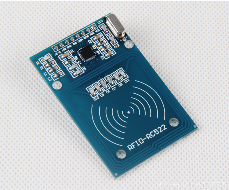
硬件准备
(基于Arduino的开发板、MFRC522读卡器模块)
Arduino Uno * 1
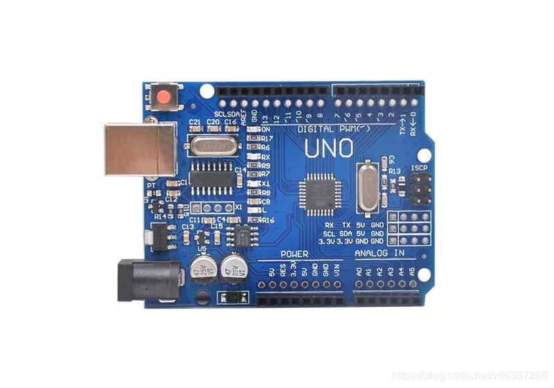
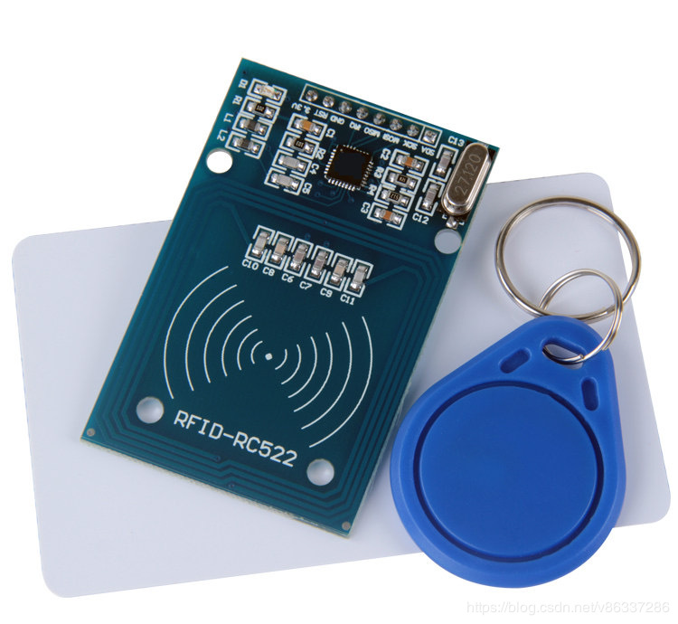
RFID-RC522 模块 * 1
IC卡 * 1-2
RFID技术现在都非常成熟和应用广泛,今天我们就来看看这个RFID如何实现读取里面的数据
接线
Arduino Uno <—> RFID-RC522
10 <—> SDA
13 <—> SCK
11 <—> MOSI
12 <—> MISO
null <—> IRQ
GND <—> GND
9 <—> RST
3.3V <—> 3.3V
需要用到RFID-RC522的库
法一、下载:https://github.com/miguelbalboa/rfid
下载解压到Arduino IDE的安装路径里的库文件夹libraries
https://download.csdn.net/download/v86337286/11813061
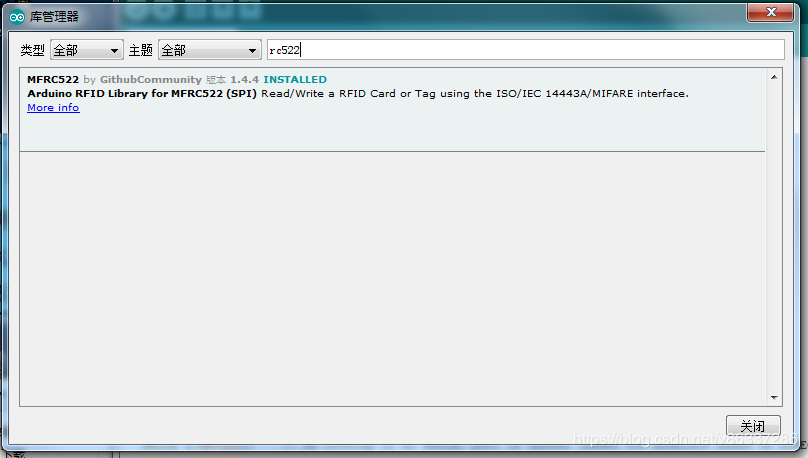
法二、点开管理库,在搜索栏里输入RC522,找到图中的库,
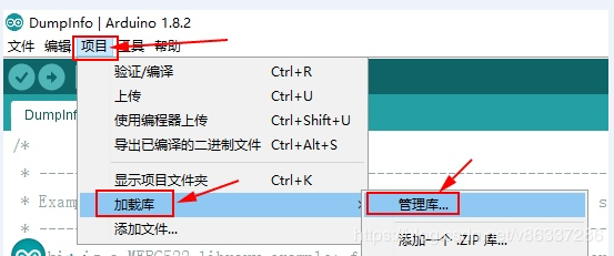
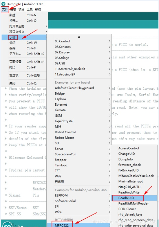
点击安装(我这图是已经安装过)
示例代码 .
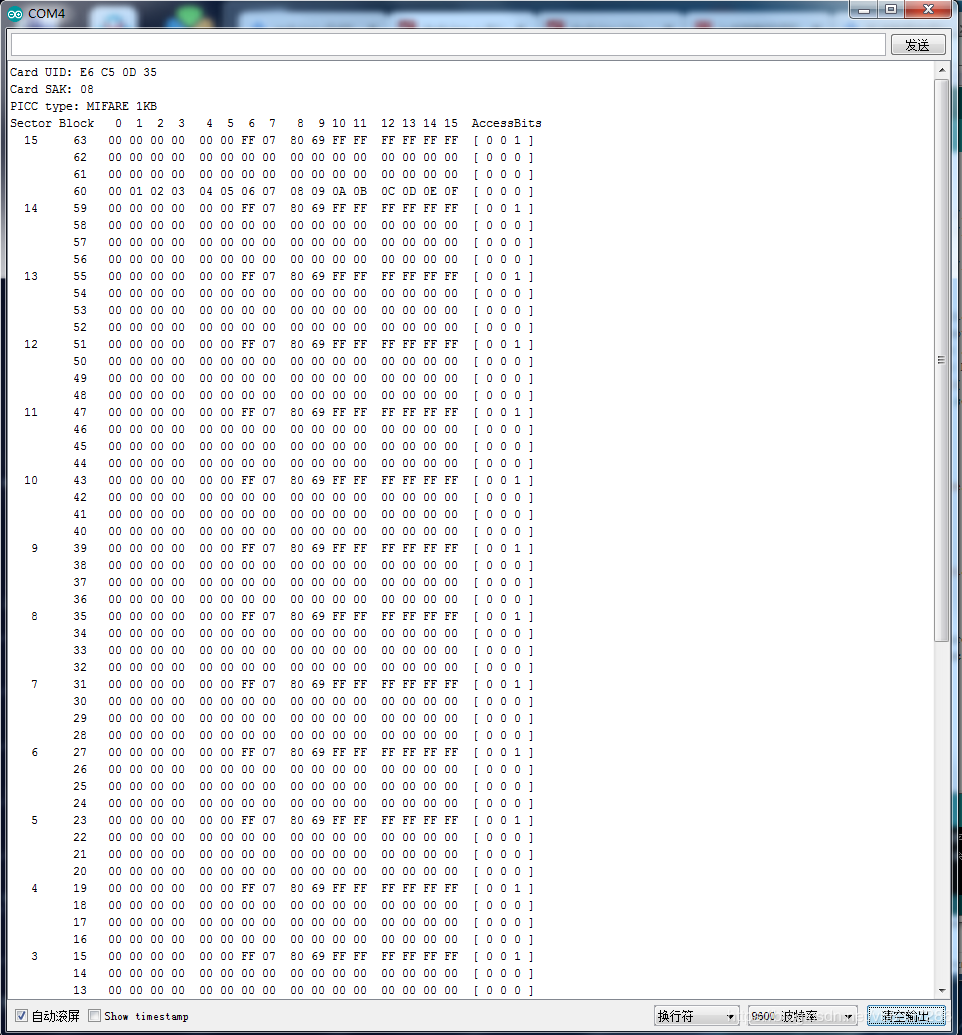
Arduino + RFID 读取 IC 卡信息
读取 IC 卡信息后并通过串口将卡号及0扇区卡号数据打印出来,其他15个扇区不显示扇区内容
代码如下
/*
 * --------------------------------------------------------------------------------------------------------------------
 * Example sketch/program showing how to read data from a PICC to serial.
 * --------------------------------------------------------------------------------------------------------------------
 * This is a MFRC522 library example; for further details and other examples see: https://github.com/miguelbalboa/rfid
 *
 * Example sketch/program showing how to read data from a PICC (that is: a RFID Tag or Card) using a MFRC522 based RFID
 * Reader on the Arduino SPI interface.
 *
 * When the Arduino and the MFRC522 module are connected (see the pin layout below), load this sketch into Arduino IDE
 * then verify/compile and upload it. To see the output: use Tools, Serial Monitor of the IDE (hit Ctrl+Shft+M). When
 * you present a PICC (that is: a RFID Tag or Card) at reading distance of the MFRC522 Reader/PCD, the serial output
 * will show the ID/UID, type and any data blocks it can read. Note: you may see "Timeout in communication" messages
 * when removing the PICC from reading distance too early.
 *
 * If your reader supports it, this sketch/program will read all the PICCs presented (that is: multiple tag reading).
 * So if you stack two or more PICCs on top of each other and present them to the reader, it will first output all
 * details of the first and then the next PICC. Note that this may take some time as all data blocks are dumped, so
 * keep the PICCs at reading distance until complete.
 *
 * @license Released into the public domain.
 *
 * Typical pin layout used:
 * -----------------------------------------------------------------------------------------
 *             MFRC522      Arduino       Arduino   Arduino    Arduino          Arduino
 *             Reader/PCD   Uno/101       Mega      Nano v3    Leonardo/Micro   Pro Micro
 * Signal      Pin          Pin           Pin       Pin        Pin              Pin
 * -----------------------------------------------------------------------------------------
 * RST/Reset   RST          9             5         D9         RESET/ICSP-5     RST
 * SPI SS      SDA(SS)      10            53        D10        10               10
 * SPI MOSI    MOSI         11 / ICSP-4   51        D11        ICSP-4           16
 * SPI MISO    MISO         12 / ICSP-1   50        D12        ICSP-1           14
 * SPI SCK     SCK          13 / ICSP-3   52        D13        ICSP-3           15
 */

#include <SPI.h>
#include <MFRC522.h>

#define RST_PIN         9          // Configurable, see typical pin layout above
#define SS_PIN          10         // Configurable, see typical pin layout above

MFRC522 mfrc522(SS_PIN, RST_PIN);  // Create MFRC522 instance

void setup() {
    Serial.begin(9600);     // Initialize serial communications with the PC
    while (!Serial);        // Do nothing if no serial port is opened (added for Arduinos based on ATMEGA32U4)
    SPI.begin();            // Init SPI bus
    mfrc522.PCD_Init();     // Init MFRC522
    mfrc522.PCD_DumpVersionToSerial();  // Show details of PCD - MFRC522 Card Reader details
    Serial.println(F("Scan PICC to see UID, SAK, type, and data blocks..."));
}

void loop() {
    // Look for new cards
    if ( ! mfrc522.PICC_IsNewCardPresent()) {
        return;
    }

    // Select one of the cards
    if ( ! mfrc522.PICC_ReadCardSerial()) {
        return;
    }

    // Dump debug info about the card; PICC_HaltA() is automatically called
    mfrc522.PICC_DumpToSerial(&(mfrc522.uid));
}
运行此代码并将其中一张卡放入RFID卡时,很多信息显示在Arduino IDE的串行监视器上
看完了上面那如何在Arduino中获得RFID的UID?
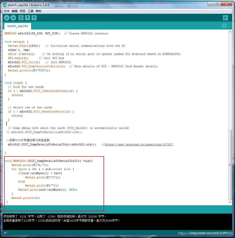
Arduino uno中只获得RFID的UID 并通过串口转发
法一
创建了另一个函数: PICC_DumpDetailsToSerialUid(Uid *uid)


函数如下
//This is just for read UID!
void MFRC522::PICC_DumpDetailsToSerialUid(Uid *uid){
Serial.print(F(“Card JUST UID :”));
for (byte i = 0; i < uid->size; i++) {
if(uid->uidByte[i] < 0x10)
Serial.print(F(" 0"));
else
Serial.print(F(" "));
Serial.print(uid->uidByte[i], HEX);
}
Serial.println();
}
可以把它放在你需要的任何地方
示例:
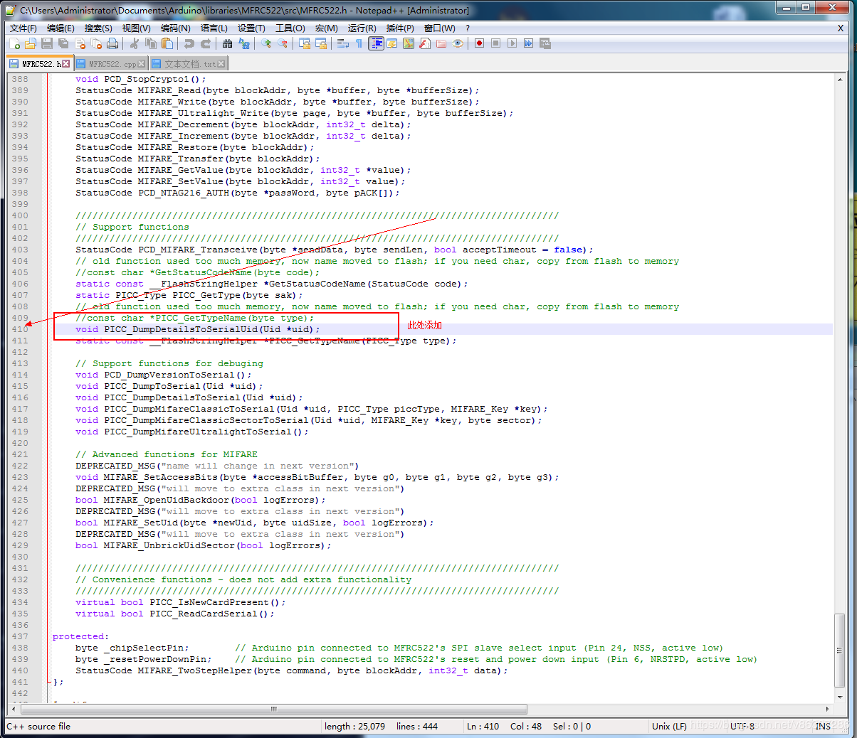
添加该功能后,您需要进入第410行的 MFRC522.h 库并添加
void PICC_DumpDetailsToSerialUid(Uid *uid);
在该库中进行了这两次编辑后,您可以在任意位置调用该函数 .
示例:
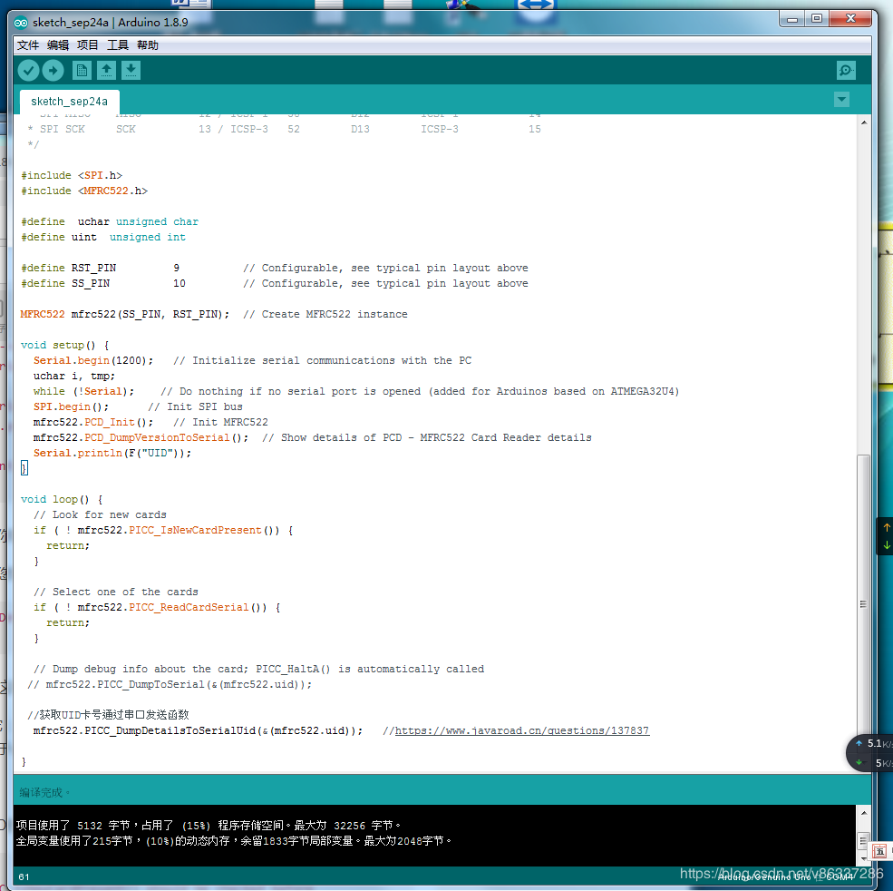
用Arduino调用它: mfrc522.PICC_DumpDetailsToSerialUid(&(mfrc522.uid)); 只仅且只有一个函数用于uid读取
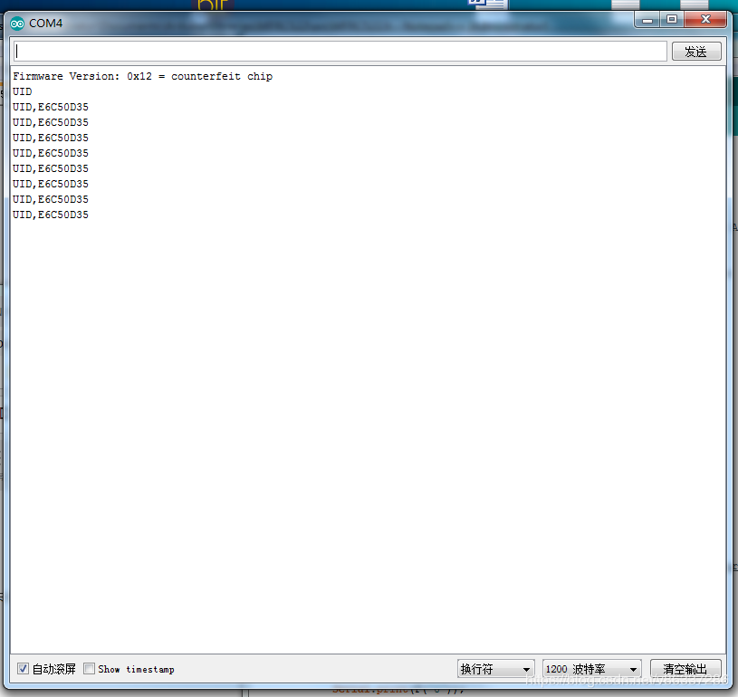
效果
法二
返回UID的函数 .
/**
 * mfrc522.PICC_IsNewCardPresent() should be checked before
 * @return the card UID
 */
unsigned long getID(){
  if ( ! mfrc522.PICC_ReadCardSerial()) { //Since a PICC placed get Serial and continue
    return -1;
  }
  unsigned long hex_num;
  hex_num =  mfrc522.uid.uidByte[0] << 24;
  hex_num += mfrc522.uid.uidByte[1] << 16;
  hex_num += mfrc522.uid.uidByte[2] <<  8;
  hex_num += mfrc522.uid.uidByte[3];
  mfrc522.PICC_HaltA(); // Stop reading
  return hex_num;
}
例如这样使用:
if(mfrc522.PICC_IsNewCardPresent()) {
  unsigned long uid = getID();
  if(uid != -1){
    Serial.print("Card detected, UID: "); Serial.println(uid);
  }
}

Arduino - Raspberry Pi,使用 D-BUS API 的蓝牙连接
如何解决Arduino - Raspberry Pi,使用 D-BUS API 的蓝牙连接
任务是使用基于python脚本的D-BUS API通过蓝牙自动实现Arduino和RaspBerry Pi之间的配对和连接过程。
连接Arduino的蓝牙模块为:Grove - Serial Bluetooth v3.0.
我能够自动化配对过程。配对脚本按顺序执行以下操作:
- 它通过创建适配器对象并使用 Startdiscovery 方法查找名为 Slave 的蓝牙模块。(命名在 Arduino 中完成)。
- 注册蓝牙代理。
- 如果设备尚未配对,则通过Pair方法创建设备对象和配对。
执行上述步骤的代码部分如下:
register_agent()start_discovery()time.sleep(10)for i in range(len(address_list)):new_dbus_device = get_device(address_list[i])dev_path = new_dbus_device.object_pathdevice_properties = dbus.Interface(new_dbus_device,"org.freedesktop.DBus.Properties")pair_status = device_properties.Get("org.bluez.Device1","Paired")if not pair_status:new_dbus_device.Pair(reply_handler=pair_reply,error_handler=pair_error,timeout=60000)
以下是 register_agent() 按要求执行的操作:
def register_agent():agent = Agent(bus,path)capability = "NoInputNoOutput"obj = bus.get_object(BUS_NAME,"/org/bluez");manager = dbus.Interface(obj,"org.bluez.AgentManager1")manager.Registeragent(path,capability)
但是,当我尝试调用 Bluez 的 device-api 中记录的 Connect 方法时,它总是失败。我创建了一个自定义串行端口配置文件并尝试了 ConnectProfile 方法,但它再次失败。
如果我使用不推荐使用的 rfcomm 工具,则通过蓝牙进行通信,或者如果我使用 python 套接字模块,它也可以工作。 但是我想避免使用 rfcomm,因为它已被弃用.关于使用python socket库,连接仅在rfcomm channel 1有效,其他通道产生Connection Refused错误。
添加MRE,以更好地阐明问题:
import dbusimport dbus.serviceimport dbus.mainloop.glibimport sysimport timeimport subprocessfrom bluezutils import *from bluetooth import *from gi.repository import GObject,GLibfrom dbus.mainloop.glib import DBusGMainLoopDBusGMainLoop(set_as_default=True)path = "/test/agent"AGENT_INTERFACE = ''org.bluez.Agent1''BUS_NAME = ''org.bluez''bus = dbus.SystemBus()device_obj = Nonedev_path = Nonedef set_trusted(path2):props = dbus.Interface(bus.get_object("org.bluez",path2),"org.freedesktop.DBus.Properties")props.Set("org.bluez.Device1","Trusted",True)class Rejected(dbus.DBusException):_dbus_error_name = "org.bluez.Error.Rejected"class Agent(dbus.service.Object):exit_on_release = Truedef set_exit_on_release(self,exit_on_release):self.exit_on_release = exit_on_release@dbus.service.method(AGENT_INTERFACE,in_signature="",out_signature="")def Release(self):print("Release")if self.exit_on_release:mainloop.quit()@dbus.service.method(AGENT_INTERFACE,in_signature="os",out_signature="")def AuthorizeService(self,device,uuid):print("AuthorizeService (%s,%s)" % (device,uuid))return@dbus.service.method(AGENT_INTERFACE,in_signature="o",out_signature="s")def RequestPinCode(self,device):set_trusted(device)return "0000"@dbus.service.method(AGENT_INTERFACE,out_signature="u")def RequestPasskey(self,device):set_trusted(device)return dbus.UInt32("0000")@dbus.service.method(AGENT_INTERFACE,in_signature="ou",out_signature="")def RequestConfirmation(self,passkey):set_trusted(device)return@dbus.service.method(AGENT_INTERFACE,out_signature="")def RequestAuthorization(self,device):return@dbus.service.method(AGENT_INTERFACE,out_signature="")def Cancel(self):print("Cancel")def pair_reply():print("Device paired and trusted")set_trusted(dev_path)def pair_error(error):err_name = error.get_dbus_name()if err_name == "org.freedesktop.DBus.Error.noreply" and device_obj:print("Timed out. Cancelling pairing")device_obj.CancelPairing()else:print("Creating device Failed: %s" % (error))mainloop.quit()def register_agent():agent = Agent(bus,capability)def start_discovery():global pi_adapterpi_adapter = find_adapter()scan_filter = dict({"DuplicateData": False})pi_adapter.SetdiscoveryFilter(scan_filter)pi_adapter.Startdiscovery()def stop_discovery():pi_adapter.Stopdiscovery()def get_device(dev_str):# use [Service] and [Object path]:device_proxy_object = bus.get_object("org.bluez","/org/bluez/hci0/dev_"+dev_str)# use [Interface]:device1 = dbus.Interface(device_proxy_object,"org.bluez.Device1")return device1def char_changer(text):text = text.replace('':'',r''_'')return textdef slave_finder(device_name):global sublist_normalsublist_normal = []sublist= []address = []edited_address = Nonesub = subprocess.run(["hcitool scan"],text = True,shell = True,capture_output=True)print(sub.stdout) #string typesublist = sub.stdout.split()for i in range(len(sublist)):if sublist[i] == device_name:print(sublist[i-1])sublist_normal.append(sublist[i-1])edited_address = char_changer(sublist[i-1])address.append(edited_address)return addressdef remove_all_paired():for i in range(len(sublist_normal)):sub = subprocess.run(["bluetoothctl remove " + sublist_normal[i]],capture_output=True)time.sleep(1)if __name__ == ''__main__'':pair_status = Noneaddress_list = slave_finder(''Slave'') #Arduino bluetooth module named as "Slave",here we are finding it.time.sleep(2)remove_all_paired() #rfcomm requires repairing after releaseprint(sublist_normal)if address_list:register_agent()start_discovery()time.sleep(10)for i in range(len(address_list)):new_dbus_device = get_device(address_list[i])dev_path = new_dbus_device.object_pathdevice_properties = dbus.Interface(new_dbus_device,"org.freedesktop.DBus.Properties")pair_status = device_properties.Get("org.bluez.Device1","Paired")if not pair_status:new_dbus_device.Pair(reply_handler=pair_reply,timeout=60000)mainloop = GLib.MainLoop()mainloop.run()
sudo btmon 输出:
Bluetooth monitor ver 5.50= Note: Linux version 5.4.83-v7l+ (armv7l) 0.832473= Note: Bluetooth subsystem version 2.22 0.832478= New Index: DC:A6:32:58:FE:13 (Primary,UART,hci0) [hci0] 0.832481= Open Index: DC:A6:32:58:FE:13 [hci0] 0.832484= Index Info: DC:A6:32:5.. (Cypress Semiconductor Corporation) [hci0] 0.832487@ MGMT Open: bluetoothd (privileged) version 1.14 {0x0001} 0.832490@ MGMT Open: btmon (privileged) version 1.14 {0x0002} 0.832540
所以问题是为什么Connect和ConnectProfile方法总是失败,我需要做什么才能在Arduino和RaspBerry Pi之间建立基于D-BUS API的蓝牙通信?
解决方法
我想你已经回答了你自己的问题。 Connect 不起作用的原因是您没有在 Raspberry Pi 上运行串行端口配置文件 (SPP)。如果您运行 btmon,您会看到客户端断开连接,因为没有与 Arduino 提供的配置文件匹配。
Python Socket 连接中使用的端口号需要与 Arduino 蓝牙模块上的端口号匹配。这可能就是只有 1 起作用的原因。
作为参考,我用 Raspberry Pi 和 HC-06 对此进行了测试。我删除了所有扫描代码以尝试获得最小的可运行代码。这是我使用的代码:
import socketfrom time import sleepimport dbusimport dbus.serviceimport dbus.mainloop.glibfrom gi.repository import GLibBUS_NAME = ''org.bluez''AGENT_IFACE = ''org.bluez.Agent1''AGNT_MNGR_IFACE = ''org.bluez.AgentManager1''ADAPTER_IFACE = ''org.bluez.Adapter1''AGENT_PATH = ''/ukBaz/bluezero/agent''AGNT_MNGR_PATH = ''/org/bluez''DEVICE_IFACE = ''org.bluez.Device1''CAPABILITY = ''KeyboardDisplay''my_adapter_address = ''11:22:33:44:55:66''my_device_path = ''/org/bluez/hci0/dev_00_00_12_34_56_78''dbus.mainloop.glib.DBusGMainLoop(set_as_default=True)bus = dbus.SystemBus()class Agent(dbus.service.Object):@dbus.service.method(AGENT_IFACE,in_signature=''o'',out_signature=''s'')def RequestPinCode(self,device):print(f''RequestPinCode {device}'')return ''0000''class Device:def __init__(self,device_path):dev_obj = bus.get_object(BUS_NAME,device_path)self.methods = dbus.Interface(dev_obj,DEVICE_IFACE)self.props = dbus.Interface(dev_obj,dbus.PROPERTIES_IFACE)self._port = 1self._client_sock = socket.socket(socket.AF_BLUETOOTH,socket.SOCK_STREAM,socket.BTPROTO_RFCOMM)def connect(self):# self.methods.Connect()self._client_sock.bind((my_adapter_address,self._port))self._client_sock.connect((self.address,self._port))def disconnect(self):self.methods.Disconnect()def pair(self):self.methods.Pair(reply_handler=self._pair_reply,error_handler=self._pair_error)def _pair_reply(self):print(f''Device trusted={self.trusted},connected={self.connected}'')self.trusted = Trueprint(f''Device trusted={self.trusted},connected={self.connected}'')while self.connected:sleep(0.5)self.connect()print(''Successfully paired and connected'')def _pair_error(self,error):err_name = error.get_dbus_name()print(f''Creating device failed: {err_name}'')@propertydef trusted(self):return bool(self.props.Get(DEVICE_IFACE,''Trusted''))@trusted.setterdef trusted(self,value):self.props.Set(DEVICE_IFACE,''Trusted'',bool(value))@propertydef paired(self):return bool(self.props.Get(DEVICE_IFACE,''Paired''))@propertydef connected(self):return bool(self.props.Get(DEVICE_IFACE,''Connected''))@propertydef address(self):return str(self.props.Get(DEVICE_IFACE,''Address''))if __name__ == ''__main__'':agent = Agent(bus,AGENT_PATH)agnt_mngr = dbus.Interface(bus.get_object(BUS_NAME,AGNT_MNGR_PATH),AGNT_MNGR_IFACE)agnt_mngr.RegisterAgent(AGENT_PATH,CAPABILITY)device = Device(my_device_path)if device.paired:device.connect()else:device.pair()mainloop = GLib.MainLoop()try:mainloop.run()except KeyboardInterrupt:agnt_mngr.UnregisterAgent(AGENT_PATH)mainloop.quit()

Arduino JSON over Serial,Json.Parse 返回意外的 JSON 输入
我修好了,谢谢大家给我指明了正确的方向。问题出在我的 Arduino 代码中。我使用的是静态 JSON,它没有给我一个压缩字符串。
我将其切换为动态,如 https://arduinojson.org/ 文档中所述。
我的 Arduino 更改为以下内容。
#include <ArduinoJson.h>

void setup() {
  // put your setup code here,to run once:
  Serial.begin(9600);
}

void loop() {
  myFunction();
  delay(5000);
}

int myFunction(){
    DynamicJsonDocument doc(260);

    int temp = 21;
    int humidity = 99;

    doc["day"] = "Monday";
    doc["temperature"] = temp;
    doc["humidity"] = humidity;

    serializeJson(doc,Serial);
    Serial.println();
  }
 在 255 个字节后为假")
Arduino Serial.Available() 在 255 个字节后为假
由于错误发生在特定字节之后,通常意味着某种溢出。您还没有显示完整的代码,响应数组的大小是多少(或 ARRAYSIZE,因为您正在使用 memset 清除它)。很可能您的 response[index] 导致越界访问
今天关于Raspberry Pi 和 Arduino 不与 Python Serial 通信和arduino和raspberry的区别的介绍到此结束,谢谢您的阅读,有关Arduino + RFID 读取 IC 卡 Arduino uno中获得RFID的UID 并通过串口转发RFID卡号、Arduino - Raspberry Pi,使用 D-BUS API 的蓝牙连接、Arduino JSON over Serial,Json.Parse 返回意外的 JSON 输入、Arduino Serial.Available() 在 255 个字节后为假等更多相关知识的信息可以在本站进行查询。
本文标签: